
Hard-coated member, and its production method

a hard-coated member and production method technology, applied in the field of members, can solve the problems of poor adhesion of pvd coatings of 3 m or more in thickness, poor chipping resistance, and restricted member materials suitable for cvd, and achieve the effects of reducing defects in the coating, high adhesion, and optimal control of residual compression

Active Publication Date: 2010-08-26
HITACHI TOOL ENG LTD
View PDF14 Cites 30 Cited by
  • Summary
  • Abstract
  • Description
  • Claims
  • Application Information

AI Technical Summary

Benefits of technology

[0016]Accordingly, an object of the present invention is to provide a hard-coated member having a thick hard coating having a residual compression stress, which is reduced to obtain high adhesion and chipping resistance without losing excellent mechanical properties such as hardness and heat resistance, thereby having excellent adhesion, wear resistance and chipping resistance.DISCLOSURE OF THE INVENTION
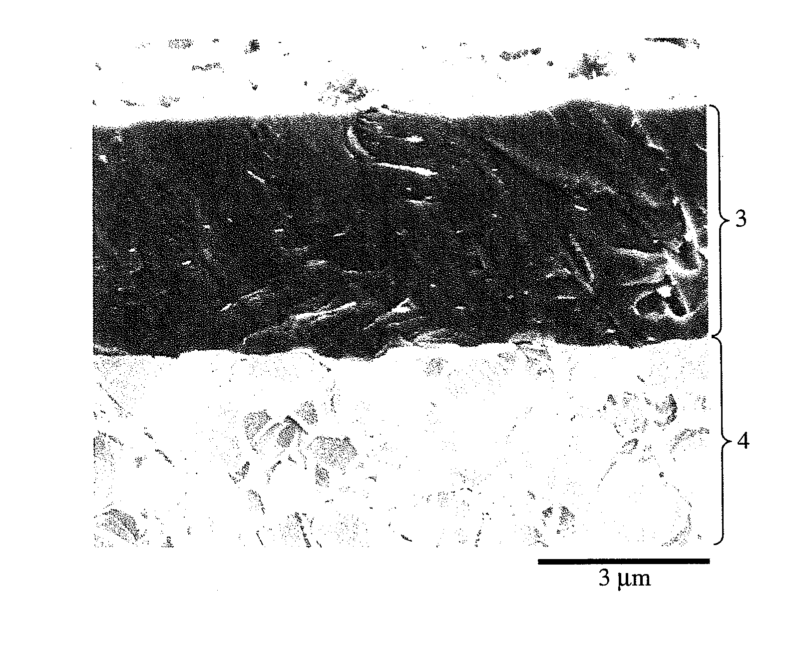
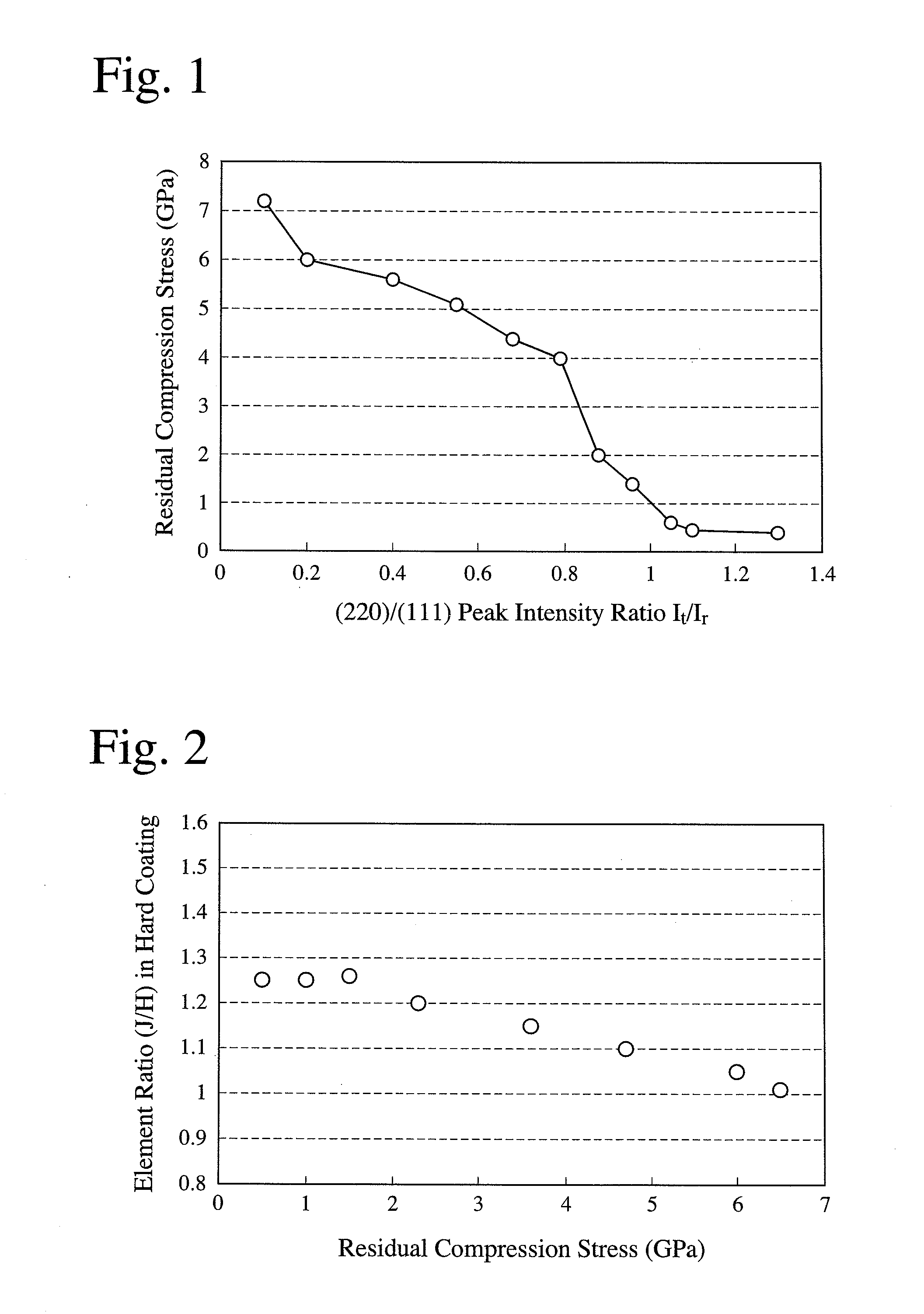
[0018]Thus, the first hard-coated member of the present invention has a hard coating having a compression stress and a thickness of 5 μm or more, the hard coating having a face-centered cubic structure having a composition represented by (Me1-aXa)α(N1-x-yCxOy), wherein Me is at least one element selected from Groups 4a, 5a and 6a, X is at least one element selected from the group consisting of Al, Si, B and S, a, x and y are respectively the contents (atomic ratios) of X, C and O, and α is a ratio of (Me1-aXa) to (N1-x-yCxOy), meeting 0.1≦a≦0.65, 0≦x≦0.1, 0≦y≦0.1, and 0.85≦α≦1.25; and the X-ray diffraction of the hard coating having a peak intensity Ir of a (111) plane, a peak intensity Is of a (200) plane, and a peak intensity It of a (220) plane, meeting 2≦Is / Ir, and 0.2≦It / Ir≦1, and the (200) plane having a half-value W(°)≦0.7. The hard-coated member of the present invention has high coating adhesion, wear resistance and chipping resistance even if the hard coating is made thick.

Problems solved by technology

For instance, CVD can form coatings as thick as 10 μm or more, which have excellent adhesion to have improved wear resistance, but are poor in chipping resistance because of residual tensile stress.
Further, because CVD temperatures are as high as about 1000° C., member materials suitable for CVD are restricted.
However, because of residual compression stress increasing as the thickness of coatings, PVD coatings of 3 μm or more in thickness are generally poor in adhesion than the CVD coatings.
However, thick coatings have large strain and thus large residual compression stress, resulting in deteriorated adhesion and chipping resistance.
However, the hard coating in Example of JP 2003-71611 A is as thin as 3 μm, poor in wear resistance.
Although a high-hardness coating is formed by as high bias voltage as 100 V or more, the residual compression stress of the coating increases as it becomes as thick as, for instance, 5 μM or more, resulting in decrease in adhesion and chipping resistance.
However, the hard coating described in JP 9-300106 A has poor crystal grain boundary strength (adhesion) at a thickness of, for instance, about 5 μm, though stress can be lowered by controlling the peak intensity of a (220) plane if the coating is as thin as about 3 μm.
Defects existing in the crystal grain boundaries increase as the hard coating becomes thicker, thereby extremely deteriorating chipping resistance.
However, this introduces many lattice defects into the hard coating, particularly defects between the TiN layers and the TiAlN layers.
Accordingly, this hard coating has poor resistance to shearing impact and thus poor chipping resistance because the lattice defects act as starting points of breakage when made thicker, despite improved abrasive wear resistance.
The formed hard coatings have high adhesion because of reduced residual compression stress, but are poorer in wear resistance than the CVD coatings because of smaller thickness.
However, it is difficult to form a uniform hard coating because it has a multi-layer structure in which component ratios change in each layer.
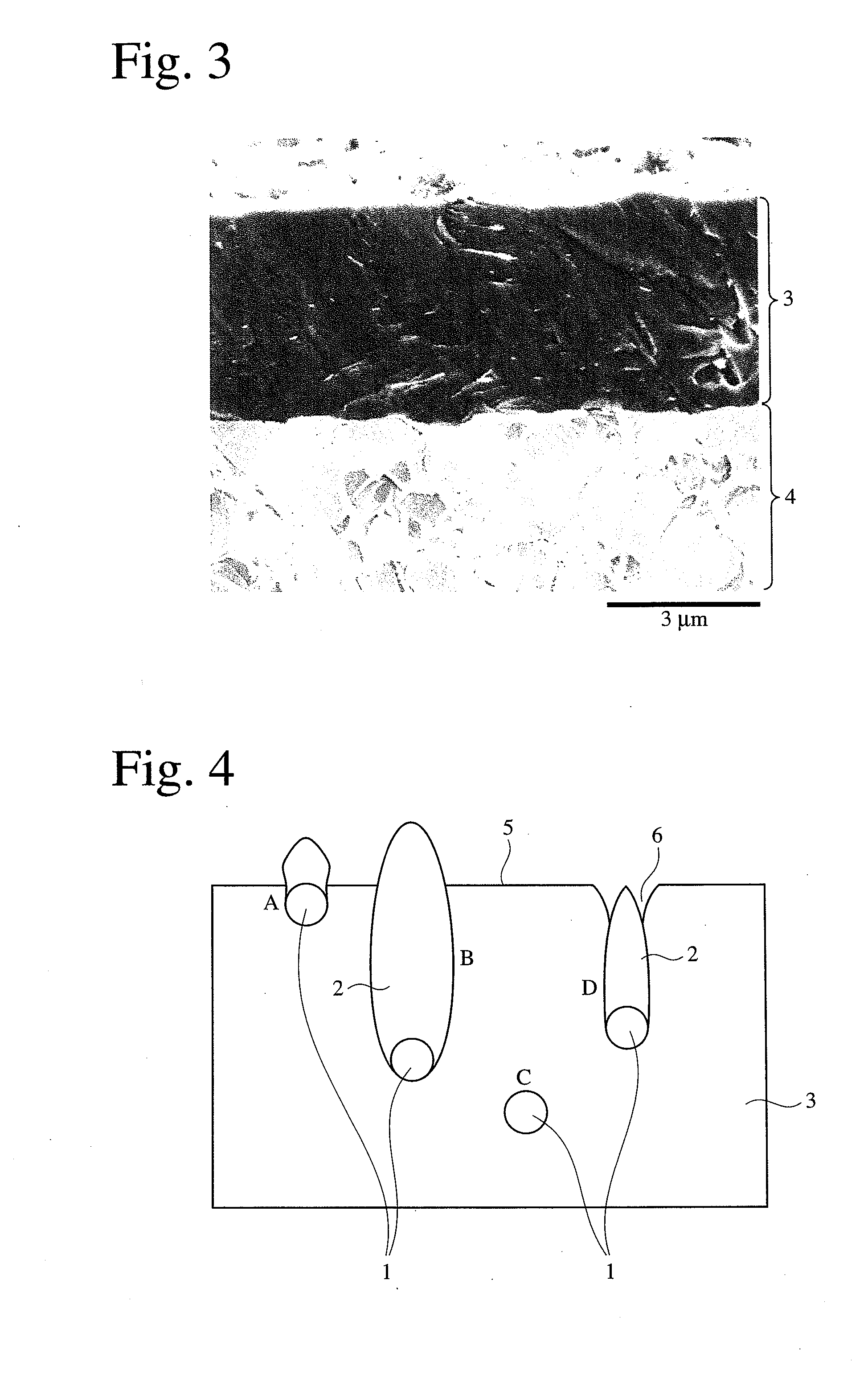
In recent high-performance machining, however, such recesses provide the surrounding coating portions with reduced mechanical strength.
Accordingly, when they are exposed on the surface after machining, the hard coating has poor impact resistance and heat resistance.
Because the exposed droplets are softer than the surrounding hard coating phase, uneven wear occurs locally, resulting in recesses on the surface, which deteriorate seizure resistance.
Also, the recessed surface has poor heat resistance, vulnerable to oxidation wear.
However, they are improvement in an apparatus, failing to eliminate droplets completely.
In addition, no consideration is made at all on droplets contained in the hard coating.
The droplets contained in the hard coating act as defects, directly deteriorating the properties of the hard coating.
As described above, conventional technologies fail to provide a thick hard PVD coating with high hardness and heat resistance as well as improved chipping resistance and wear resistance, without deteriorating adhesion to a substrate and mechanical strength to impact from outside.

Method used


Image

  • Hard-coated member, and its production method
  • Hard-coated member, and its production method
  • Hard-coated member, and its production method

Examples


examples within

[0160]Samples 84 and 85 (Examples within the Present Invention)

[0161]Samples were produced in the same manner as in Sample 1, except for coating hexagonal crystal materials as outermost layers of the hard coatings to increase lubrication. Sample 84 had an outermost layer of TiB2, and Sample 85 had an outermost layer of WC.

[0162]Samples 86-88 (Examples within the Present Invention)

[0163]Samples were produced in the same manner as in Sample 1, except for forming a 10-nm Ti layer (Sample 86), a 200-nm Cr layer (Sample 87), and a 210-nm TiAl alloy layer (Sample 88) as metal layers immediately on the substrates to increase adhesion.

[0164]Samples 113-115 (Conventional Examples)

[0165]Samples were produced in the same manner as in Sample 1 except for changing the composition and thickness as shown in Table 1, with a coating temperature of 450-500° C. and a DC bias voltage of −50 V, which were generally used.

[0166]Samples 116-117 (Conventional Examples)

[0167]Samples were produced in the same...


PUM

PropertyMeasurementUnit
thicknessaaaaaaaaaa
thicknessaaaaaaaaaa
temperatureaaaaaaaaaa

Abstract

The hard-coated member of the present invention having a compression-stress-loaded hard coating having a thickness of 5 μm or more, the hard coating having a face-centered cubic structure having a composition represented by (Me1-aXa)α(N1-x-yCxOy), wherein Me is at least one element selected from Groups 4a, 5a and 6a, X is at least one element selected from the group consisting of Al, Si, B and S, a, x and y are respectively the contents (atomic ratios) of X, C and O, and α is a ratio of (Me1-aXa) to (N1-x-yCxOy), meeting 0.1≦a≦0.65, 0≦x≦0.1, 0≦y≦0.1, and 0.85≦α≦1.25; and the X-ray diffraction of the hard coating having a peak intensity Ir of a (111) plane, a peak intensity Is of a (200) plane, and a peak intensity It of a (220) plane, meeting 2≦Is / Ir, and 0.2≦It / Ir≦1, and the (200) plane having a half-value W(°)≦0.7.

Description

CROSS REFERENCE TO RELATED APPLICATION[0001]This application is a National Stage of International Application No. PCT / JP2007 / 069993, filed Oct. 12, 2007, the contents of which is incorporated herein by reference in its entirety.FIELD OF THE INVENTION[0002]The present invention relates to a member used for machining metal parts, etc., particularly to a hard-coated member having a hard coating on a surface required to have high wear resistance and chipping resistance, and its production method.BACKGROUND OF THE INVENTION[0003]Recent metal-machining tools, sliding members, etc. are produced by forming hard coatings having high hardness and heat resistance on members of high-speed steel or cemented carbide. Coating technologies include chemical vapor deposition (CVD) for forming hard coatings with residual tensile stress, and physical vapor deposition (PVD) for forming hard coatings with residual compression stress. CVD-coated members are mainly used for turning, while PVD-coated member...

Claims


Application Information

Patent Timeline
Patent Type & Authority Applications(United States)
IPC IPC(8): B32B3/00B32B9/00B32B15/04
CPCC23C14/0641C23C14/0664C23C14/0676Y10T428/24612C23C30/005Y10T428/26Y10T428/265C23C14/325
Inventor KUBOTA, KAZUYUKIOHNUMA, HITOSHI
Owner HITACHI TOOL ENG LTD
Learn More