
Electric Double Layer Capacitor

a double-layer capacitor and capacitor technology, applied in the direction of electrolytic capacitors, electrolytic capacitors, electrolytic capacitors, etc., can solve the problems of reducing the capacitance density, increasing the heat generation, increasing the energy loss, etc., and reducing the durability. , to achieve the effect of enhancing the durability and/or safety of the electric double-layer capacitor suited to such applications, and moldability of the polarized electrode layer

Inactive Publication Date: 2010-09-02
W L GORE & ASSOC GK
View PDF6 Cites 12 Cited by
  • Summary
  • Abstract
  • Description
  • Claims
  • Application Information

AI Technical Summary

Benefits of technology

[0013]It is a further object of the present invention to improve the durability of the electric double layer capacitor suited to the above applications.
[0014]It is a still further object of the present invention to improve the safety of the electric double layer capacitor suited to the above applications.
[0015]It is a yet further object of the present invention to improve the moldability of polarizable electrode layers to be used in the electric double layer capacitor suited to the above applications.
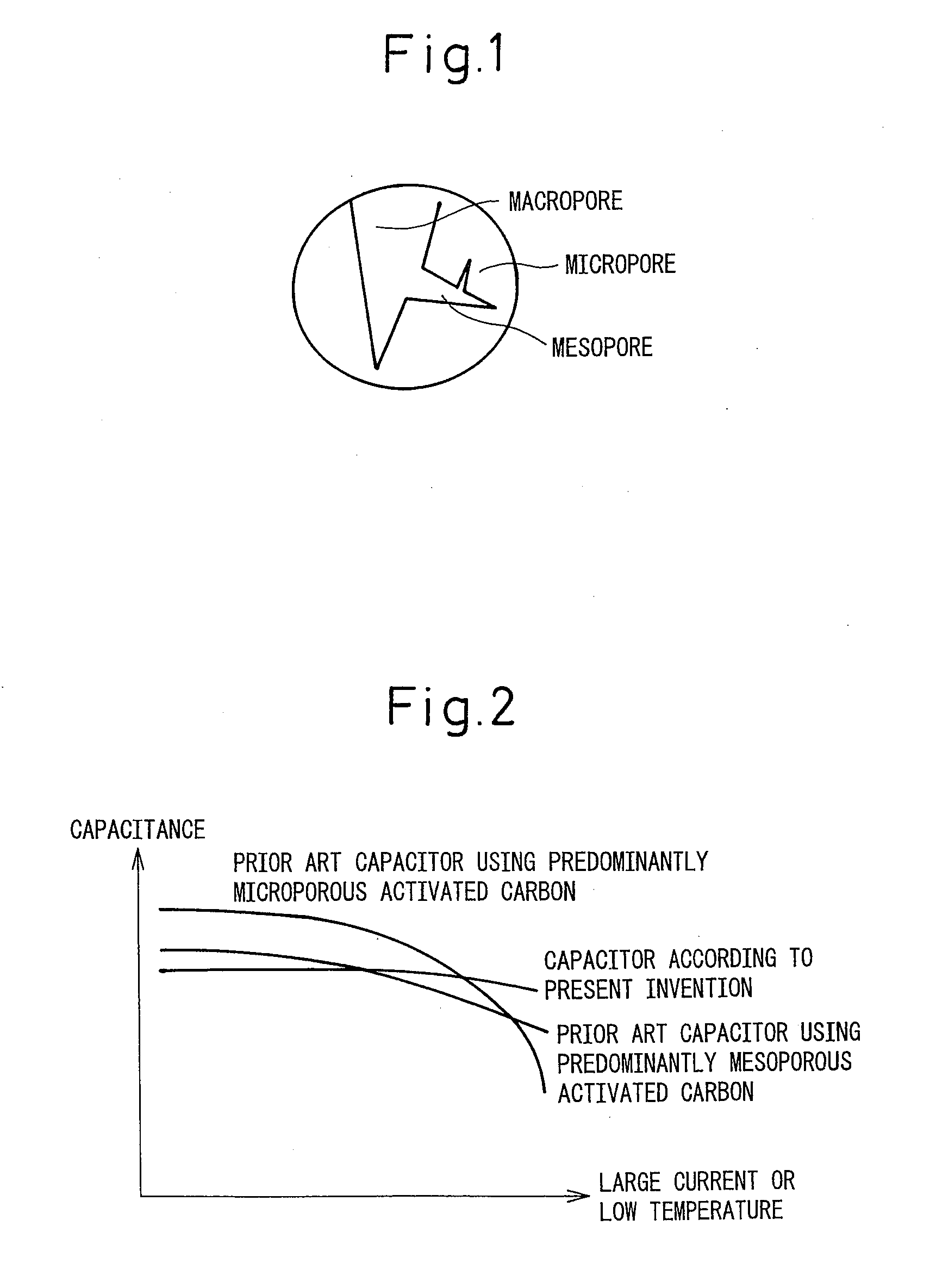
[0052]According to the present invention, an electric double layer capacitor can be achieved that is suited to large current, quick discharge applications requiring large current such as 100 mA / cm2 or larger, and / or applications in a low-temperature environment such as −20° C. or lower. Further, according to the present invention, the durability and / or safety of the electric double layer capacitor suited to such applications are enhanced. Furthermore, according to the present invention, the moldability of the polarizable electrode layers for the electric double layer capacitor suited to such applications improves.

Problems solved by technology

However, if such polarizable electrode layers are used in applications that require a current of 10 mA / cm2 or larger, problems such as the decrease of capacitance density, increase of energy loss, increase of heat generation, etc. become pronounced, because the mobility of electrolyte ions within the pores is limited.
There is also the problem that, after long use, residues of decomposed materials may clog the pores, which can significantly degrade the durability.
However, none of Japanese Unexamined Patent Publications Nos. 2000-340470, H08-119614, 2001-316103, and 2001-89119 pay attention to the mobility of electrolyte ions in spaces other than the pores of the activated carbon (that is, the spaces in the interstices between the particles of the activated carbon, carbon black, etc. in the polarizable electrode layers), and it cannot be said that the method is effective enough in suppressing the performance drop.
Especially, in the case of a large current discharge at 100 mA / cm2 or larger, the mobility of electrolyte ions is insufficient, and problems such as the decrease of capacitance density, increase of energy loss, increase of heat generation, etc. become pronounced.
On the other hand, in the case of a discharge at low temperatures of −20° C. or lower, the resistance increases and, as a result, the capacitance density decreases, thus limiting applications in a low-temperature environment.
Such methods, however, have had the problem that it is difficult to control the voids and the capacitance density decreases excessively.
Furthermore, when performing heat treatment, there have been such problems as the pores of the activated carbon being shrunk under heat and an inability to use a polymer binder because of its heat resistance problem, and when performing cleaning by dissolving in a solvent, there has been the problem that the durability decreases because the solvent is adsorbed on the activated carbon; because of these and other problems, the above method has not been practicable.
However, the fabrication of the polarizable electrode layers using such natural activated carbon has involved the problem that the material is difficult to mold because of such problems as the crushing of particles during molding and the sliding characteristics of the particles.
That is, cracks can easily occur in the polarizable electrode layers, the reduction in film thickness by rolling is small, and so forth.
The solvent is removed by drying after molding the polarizable electrode layers, but it is difficult to completely remove the solvent, and if the solvent remains in the pores of the activated carbon, the durability of the capacitor decreases.
Further, there are cases where a low-viscosity nitrile-based organic solvent, such as an acetonitrile solvent, is used in order to improve the large current and low temperature characteristics, but since nitrile-based organic solvents generate toxic cyanide gas when burning, using such solvents is not desirable from the standpoint of safety.

Method used


Image

  • Electric Double Layer Capacitor
  • Electric Double Layer Capacitor
  • Electric Double Layer Capacitor

Examples


working examples

[0086]The present invention will be described in detail below with reference to working examples.

working example 1

[0087]A coconut shell as a material for activated carbon was heated at 800° C. in an inert atmosphere to obtain a carbonized material, which was then steam-activated for 120 minutes at 900° C. After that, the material was cooled to room temperature, rinsed with water, and dried. The thus produced activated carbon was milled by a jet mill, and the particles were classified to obtain activated carbon having a particle size distribution with a mode diameter of 20 μm (relative particle quantity: 15%) in which 50% of the particles were contained within the range of ±30% of the mode diameter (the range of 14 to 26 μm). The pore volume of the resulting activated carbon was 1.07 cm3 / g, the specific surface area was 2000 m2 / g, and the external specific surface area was 1500 m2 / g.

[0088]30% by mass of ethanol was added to a mixture consisting of 85% by mass of the activated carbon, 5% by mass of Ketjen black powder as a conductive agent (“EC600JD” manufactured by Ketjen Black International Co....

working example 2

[0089]Working example 1 was repeated except that the activation time was 90 minutes, the pore volume was 0.93 cm3 / g, the specific surface area was 1600 m2 / g, and the external specific surface area was 1100 m2 / g. The number of rolling passes required to form the 150-μm thick electrode sheet was two, which was the same as Working example 1. The electrode density of the obtained electrode sheet was 0.52 g / cm3, the external specific surface area per unit volume of the electrode sheet was 486 m2 / cm3, the pore volume of the entire electrode sheet was 0.98 cm3 / g, and the volume based on the inter-particle interstices per unit volume of the electrode sheet was 0.10 cm3 / cm3.


PUM


Abstract

Disclosed is an electric double layer capacitor comprising a polarizable electrode layer that contains an activated carbon, a conductive agent, and a binder, wherein an external specific surface area of the activated carbon (defined as a specific surface area calculated from a nitrogen absorption isotherm by a t-plot method by excluding micropores of pore diameter smaller than 20 angstroms), per unit volume of the polarizable electrode layer, lies within a range of 450 to 800 m2 / cm3, and a volume based on inter-particle interstices per unit volume of the polarizable electrode layer lies within a range of 0.05 to 0.12 cm3 / cm3. The electric double layer capacitor according to the present invention is particularly suited to large current, quick discharge applications.

Description

TECHNICAL FIELD[0001]The present invention relates to an electric double layer capacitor.BACKGROUND ART[0002]In recent years, electric double layer capacitors capable of charging and discharging with a large current have been attracting attention as electric power storage devices that hold promise for applications requiring frequent charge / discharge cycles, for example, as auxiliary power sources for electric vehicles, solar cells, wind power generation, etc. There is therefore a need for an electric double layer capacitor that has high energy density, is capable of fast charging and discharging, and has excellent durability.[0003]An electric double layer capacitor comprises a pair of polarizable electrode layers as an anode and cathode disposed opposite each other with a separator interposed therebetween. Each polarizable electrode layer is impregnated with an aqueous or non-aqueous electrolytic solution, and is united with a current collector. With the aqueous type electrolytic so...

Claims


Application Information

Patent Timeline
Patent Type & Authority Applications(United States)
IPC IPC(8): H01G9/058H01G9/155H01G11/22H01G11/14H01G11/24H01G11/28H01G11/34H01G11/38H01G11/42H01G11/44H01G11/54H01G11/60H01G11/86
CPCH01G9/038H01G11/42H01G11/32Y02T10/7022H01G11/24Y02E60/13Y02T10/70H01G11/60
Inventor NORIEDA, HIROYUKIKOBAYASHI, KOTARO
Owner W L GORE & ASSOC GK
Learn More