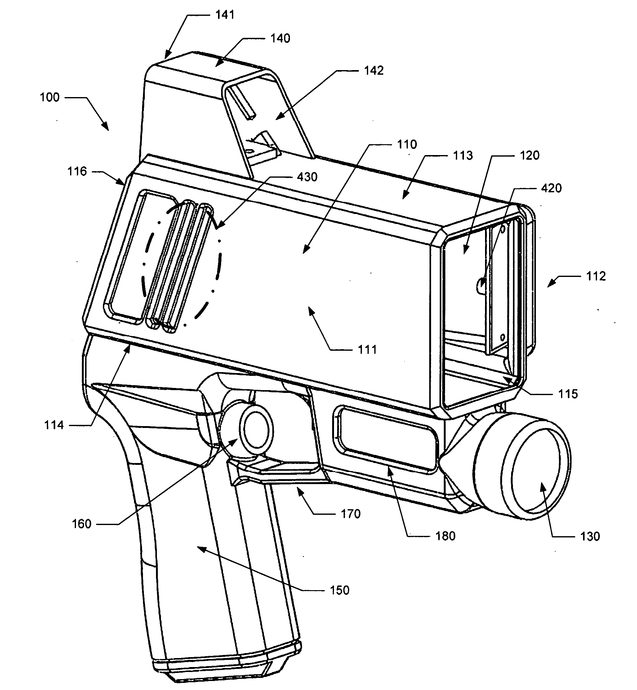
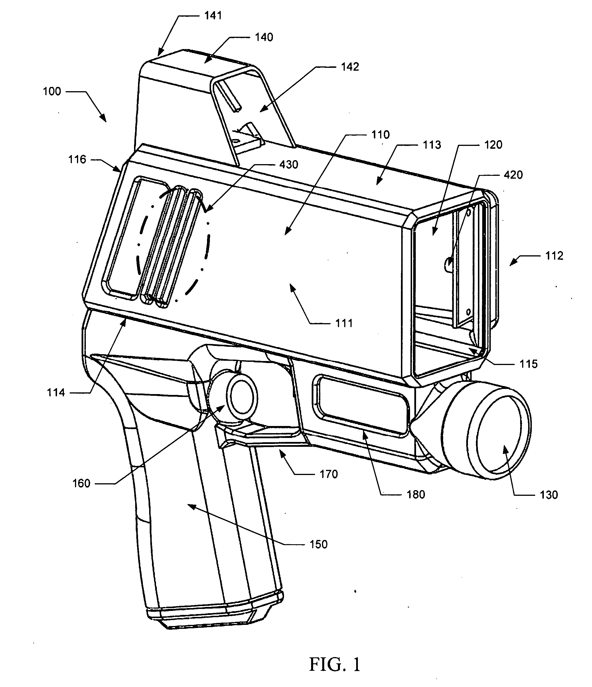
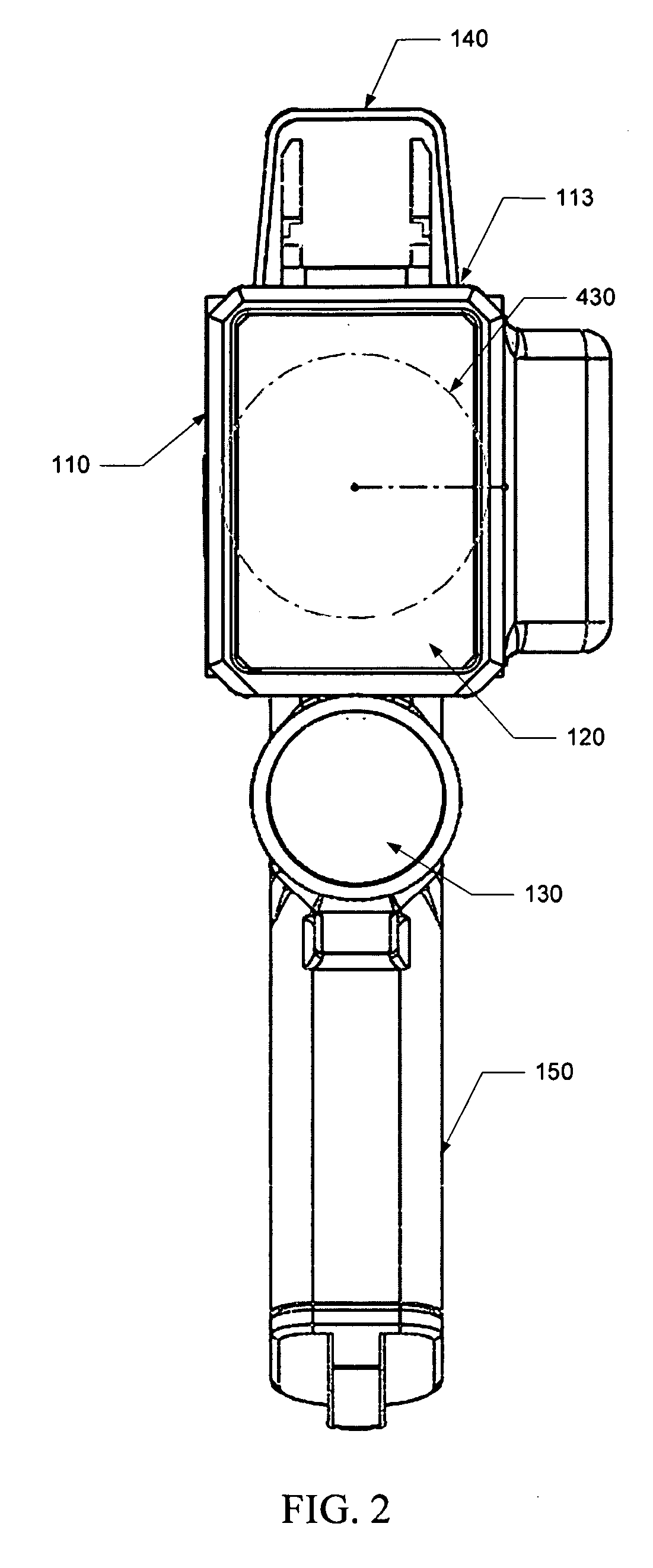
[0010]The reflective surface is positioned in the housing to be aligned with an optical opening in the housing. The reflective surface is positioned to receive the return laser pulse or pulses from the target through the optical opening. The reflective surface is sufficiently large in size to collect enough light to enable the receiver to detect the return laser pulse or pulses from the target. The reflective surface has a shape that enables the flat, affectively collimated
wavefront of the return laser pulse or pulses to be directed to a focal point at which the receiver (e.g., a
photodiode) is positioned in the housing. In various embodiments, the reflective surface is concave. For example, in one embodiment, the reflective surface is a segment of a parabola. Furthermore, in various embodiments, the reflective surface is composed of plastic or other rigid, durable, lightweight material with a reflective
coating (e.g., aluminum, gold, etc.) formed thereon. The reflective surface may be used in lieu of a lens to focus return
laser light, thereby better distributing or reducing the weight of the device. In various embodiments, the reflective surface is mounted in a housing of the device to direct the received laser pulse to an off-axis focal point outside of the collection area of the housing in which the return laser pulse is received. This configuration enables the receiver to be positioned so as not to obstruct the collection area in front of the reflective surface, thereby enabling the reflective surface to focus more of the reflected laser pulse to the receiver. A positioner mounted to the housing may be used to orient the receiver at the reflective surface's focal point. The housing may define an focal portion in which to accommodate the receiver and positioner.
[0011]In an alternative embodiment, the LIDAR device comprises a second, separate reflective surface interposed in the
optical path from the transmitter to the optical opening from which laser pulse or pulses exits the housing. The transmitter may act as a
point source, or approximately so, and the light of laser pulse or pulses generated by it are divergent so that the beam width increases to a degree as the light travels to the reflective surface. The second reflective surface is positioned in the housing to receive the light from the transmitter, and is shaped to collimate the light of the laser pulse or pulses so that its rays travel in parallel with a flat
wavefront from the LIDAR device. Thus, in various embodiments, the second reflective surface sends the light out in the same direction as the collection area receives the reflected laser pulses. This collimation attained through the reflective surface enables a laser pulse with greater
optical intensity to be directed more precisely to the target, thereby generating a stronger return laser pulse. The second reflective surface can be structured and composed of similar materials as the first reflective surface used in the reception
optical path, and can be used to achieve better
weight distribution and balance by eliminating a relatively heavy lens positioned in the front of the device.
[0015]In various embodiments, the device also includes a heads-up display configured for use by an operator of the device to
sight the target. The heads-up display includes a display element positioned to oppose a transparent element of a combiner arranged within the
field of view defined in the heads-up display. The processor generates a display
signal indicating
target range or velocity or other parameter regarding the target, in response to the
time signal. The processor outputs the display
signal to a display element such as a light-emitting
diode (LED), organic light-emitting
diode (
OLED), or
liquid crystal display (LCD) which is arranged to illuminate the transparent element of the combiner within the
field of view of the heads-up display. An operator of the device can therefore view the target while simultaneously viewing the target's range or velocity or other
state parameter within one
field of view, thus providing greater ease of operation of the device.
[0016]In another embodiment, a single reflective surface is positioned in the housing relative to the transmitter, receiver and optical opening or openings of the housing so as to be common to both the transmission and reception paths of the laser pulse or pulse
train. Thus, a laser pulse or pulse
train from the transmitter is reflected and collimated by the reflective surface, and is directed through an optical opening in the housing to the target. The return laser pulse or pulses is received through an optical opening in the housing, and impinges upon the same reflective surface which is shaped to focus the return laser pulse or pulses to a focal point at which the receiver is positioned within the housing. Thus, the reflective surface serves to both collimate transmitted laser pulses and focus received laser pulses, greatly simplifying device configuration and achieving economization in the materials used to manufacture the device.


