Eureka AIR delivers breakthrough ideas for toughest innovation challenges, trusted by R&D personnel around the world.

Separator for nonaqueous electrolyte battery and nonaqueous electrolyte battery

Active Publication Date: 2010-09-16
SANYO ELECTRIC CO LTD +1
View PDF4 Cites 39 Cited by
  • Summary
  • Abstract
  • Description
  • Claims
  • Application Information

AI Technical Summary

Benefits of technology

[0041]The porous layer in the present invention is, as described previously, a porous layer in which a resin binder is less likely to be oxidatively decomposed even if the potential of the positive electrode is above 4.40 V (vs. Li / Li+). Therefore, if the porous layer is disposed on the positive electrode side of the porous separator substrate, the above effects of the invention are particularly pronounced.
[0042]Furthermore, in nonaqueous electrolyte secondary batteries whose positive electrodes have an end-of-charge voltage of above 4.40 V (vs. Li / Li+), the above effects of the invention are more pronounced. Therefore, the nonaqueous electrolyte secondary battery according to the present invention is preferably a nonaqueous electrolyte secondary battery whose positive electrode is capable of being charged to above 4.40 V (vs. Li / Li+).
[0043]The nonaqueous electrolyte battery according to the present invention may be a primary battery but is preferably a nonaqueous electrolyte secondary battery.
[0044]The positive electrode in the present invention is not particularly limited so long as it is a positive electrode used in a nonaqueous electrolyte battery. Examples of an active material for the positive electrode include lithium cobaltate, lithium-nickel composite oxides, such as lithium nickelate, lithium-transition metal composite oxides as represented by LiNixCOyMnzO2 (x+y+z=1), and olivine phosphate compounds.
[0045]The negative electrode that can be used in the present invention is not limited so long as it can be used as a negative electrode for a nonaqueous electrolyte battery. Examples of an active material for the negative electrode include carbon materials, such as graphite and coke, tin oxide, metal lithium, and metals capable of forming an alloy with lithium, such as silicon.
[0046]The nonaqueous electrolyte in the present invention is not particularly limited so long as it can be used for nonaqueous electrolyte batteries. Examples of a lithium salt in the electrolyte include LiBF4, LiPF6, LiN(SO2CF3)2, LiN(SO2C2F5)2, and LiPF6-x(CnF2n+1)x where 1<x<6 and n=1 or 2. One of these materials or a mixture of two or more of them can be used as the lithium salt. The concentration of the lithium salt is not particularly limited but is preferably approximately 0.8 to approximately 1.5 mol / l.

Problems solved by technology

If an organic solvent is used in order to dissolve polyamide, polyimide, polyamideimide or like resin, the organic solvent may cause a problem in that it will dissolve poly(vinylidene fluoride) (PVdF) used as a binder for a positive electrode.
Therefore, in disposing a porous layer between an electrode and a separator, the porous layer cannot be placed on the surface of a positive electrode and must be placed on the surface of the separator facing the positive electrode.
If the porous layer is placed on the positive electrode side of the separator in this manner, this may cause a problem in that when the battery voltage is above 4.30 V (above 4.40 V (vs.
Li / Li+)), the high-temperature charge characteristic of the battery may be largely deteriorated.
Li / Li+), the resin such as polyamide, polyimide or polyamideimide in the porous layer adjacent to the positive electrode surface is oxidatively decomposed and a reaction product derived from the oxidative decomposition has an adverse effect on intercalation reaction of lithium in the interior of the battery.
However, these bonds are poor in resistance to electrophilic reaction, and polyimide resins tend to be oxidatively decomposed when used in the vicinity of the positive electrode.

Method used


Image

  • Separator for nonaqueous electrolyte battery and nonaqueous electrolyte battery
  • Separator for nonaqueous electrolyte battery and nonaqueous electrolyte battery

Examples


example a1

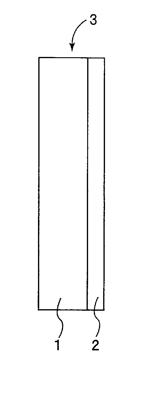
Production of Separator

Synthesis of Fluorine-Containing Resin

[0055]In a four-necked flask provided with a condenser and a nitrogen gas inlet, 1.0 mol of 2,2-bis(3,4-dicarboxyphenyl)hexafluoropropane dianhydride and 0.95 mol of o-tolidine diisocyanate were mixed with N-methyl-2-pyrrolidone (NMP) to give a solid content concentration of 20% by weight, and 0.01 mol of diazabicycloundecene was added as a catalyst to the mixture. The mixture was stirred and allowed to react at 120° C. for four hours.

[0056]The solvent-soluble polyimide resin thus obtained had a solid content concentration of 20% by weight and a logarithmic viscosity of 0.7 g / dl, and the content of fluorine atoms in the resin was 18% by weight.

Preparation of Application Liquid

[0057]Next mixed were 10 parts by weight of the obtained solvent-soluble polyimide resin solution (solid content: 20% by weight), 12 parts by weight of polyethylene glycol (trade name “PEG-400”, manufactured by Sanyo Chemical Industries, Ltd.), 40 par...

example a2

[0073]A separator was produced in the same manner as in Example A1 except that the polyimide resin and titanium oxide were mixed to give a ratio of 10 parts by weight of polyimide resin to 90 parts by weight of titanium oxide in the porous layer.

example a3

[0074]A separator was produced in the same manner as in Example A1 except that the polyimide resin and titanium oxide were mixed to give a ratio of 15 parts by weight of polyimide resin to 85 parts by weight of titanium oxide in the porous layer.


PUM


Abstract

To obtain a separator for a nonaqueous electrolyte battery that has an excellent nonaqueous electrolyte permeability into an electrode and an excellent electrolyte retentivity of the electrode and achieves a large capacity, a high energy density and a good high-temperature charge characteristic. A separator 3 used for a nonaqueous electrolyte battery is formed by disposing a porous layer 2 made of inorganic fine particles and a resin binder on a porous separator substrate 1, the resin binder is made of at least one resin selected from the group consisting of polyimide resins, polyamide resins and polyamideimide resins and the molecular chain of the resin has a halogen atom content of 10% to 30% by weight, and the content of the resin binder in the porous layer is 5% by weight or more.

Description

TECHNICAL FIELD[0001]This invention relates to separators used for nonaqueous electrolyte batteries, such as lithium ion secondary batteries and polymer secondary batteries, and relates to nonaqueous electrolyte batteries using the separators.BACKGROUND ART[0002]In recent years, size and weight reduction of mobile information terminals, such as cellular phones, notebook computers and PDAs, has rapidly progressed. Batteries serving as their driving power sources are being required to achieve a much higher capacity. Among various types of secondary batteries, lithium ion batteries having particularly high energy densities have increased the capacity over the years, but under the existing conditions cannot fully respond to the above requirement. In addition, recently, the application of lithium ion batteries has been expanded beyond mobile information terminals, such as cellular phones, to serve as middle to large size batteries for electric tools, electric cars or hybrid cars by takin...

Claims


Application Information

Patent Timeline
IPC IPC(8): H01M2/16H01M10/058H01M50/451H01M50/489H01M50/491
CPCH01M2/166H01M2/1686Y02T10/7011Y02E60/122H01M10/052Y02E60/10H01M50/446Y02P70/50H01M50/489H01M50/451H01M50/491H01M50/414H01M50/423H01M50/431H01M10/02H01M10/0525Y02T10/70
Inventor BABA, YASUNORIIMACHI, NAOKINAKAJIMA, ATSUSHIIRIE, MICHIHIKONAKAMURA, MASANORI
Owner SANYO ELECTRIC CO LTD
Why Eureka
Eureka Blog
Learn More