Mechanical component and rolling bearing
a technology of rolling bearings and components, applied in the direction of solid-state diffusion coating, climate sustainability, metallic material coating processes, etc., can solve the problems of contaminated environment, smearing of rolling bearings, damage to rolling bearings employed in high-speed rotation, etc., to suppress the reduction of hardness of bearing components, the effect of sufficient fatigue resistan
- Summary
- Abstract
- Description
- Claims
- Application Information
AI Technical Summary
Benefits of technology
Problems solved by technology
Method used
Image

Examples
first embodiment
[0120]Initially the present invention in a first embodiment will be described.
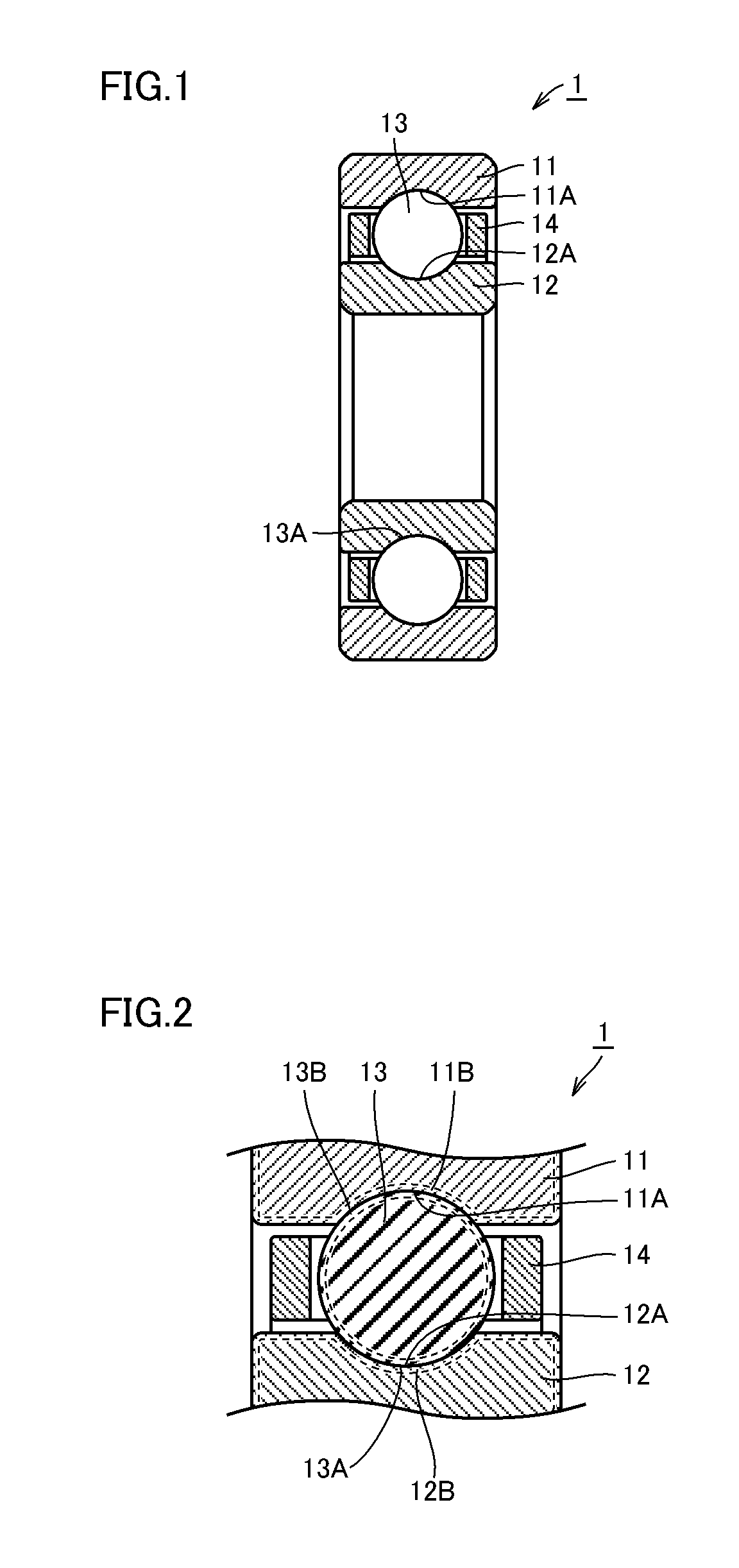
[0121]With reference to FIG. 1, a deep groove ball bearing 1 includes an annular outer ring 11, an annular inner ring 12 arranged to be inner than outer ring 11, and rolling elements implemented as a plurality of balls 13 arranged between outer and inner rings 11 and 12 and held in an annular cage 14. Outer ring 11 has an inner circumferential surface having an outer ring raceway surface 11A and inner ring 12 has an outer circumferential surface having an inner ring raceway surface 12A. Outer ring 11 and inner ring 12 are disposed such that inner ring raceway surface 12A and outer ring raceway surface 11A face each other. The plurality of balls 13 are held in a rollable manner on an annular raceway, with their rolling contact surfaces 13A in contact with inner ring raceway surface 12A and outer ring raceway surface 11A, disposed at a predetermined pitch in the circumferential direction by means of cage 14....
second embodiment
[0155]With reference to FIG. 12, the present invention in a second embodiment provides a turbo fan engine configured, as will be described hereinafter.
[0156]Referring to FIG. 12, a turbofan engine 70 includes a compression portion 71, a combustion portion 72 and a turbine portion 73. Turbofan engine 70 further includes a low-pressure main shaft 74 so arranged as to reach turbine portion 73 from compression portion 71 through combustion portion 72 and a high-pressure main shaft 77 so arranged as to enclose the outer circumferential surface of low-pressure main shaft 74.
[0157]Compression portion 71 includes a fan 75 having a plurality of fan blades 75A connected to low-pressure main shaft 74 and so formed as to radially outwardly protrude from low-pressure main shaft 74, a fan nacelle 76 enclosing the outer peripheral side of fan 75 and extending toward combustion portion 72 and a compressor 81 arranged on the side closer to combustion portion 72 as viewed from fan 75. Compressor 81 h...
third embodiment
[0190]The present invention in a third embodiment will now be described. A mechanical component according to the third embodiment is basically similar in structure to the case of the first embodiment, and can be similarly produced. However, the third embodiment is different from the first embodiment in the component composition of steel serving as a material and a heat treatment method, as described below.
[0191]Referring to FIG. 1 and FIG. 2, outer ring 11, inner ring 12, and ball 13 serving as mechanical components in the third embodiment are constituted of steel containing at least 0.11 mass % and not more than 0.15 mass % of carbon, at least 0.1 mass % and not more than 0.25 mass % of silicon, at least 0.15 mass % and not more than 0.35 mass % of manganese, at least 3.2 mass % and not more than 3.6 mass % of nickel, at least 4 mass % and not more than 4.25 mass % of chromium, at least 4 mass % and not more than 4.5 mass % of molybdenum and at least 1.13 mass % and not more than 1...
PUM
| Property | Measurement | Unit |
|---|---|---|
| Percent by mass | aaaaa | aaaaa |
| Percent by mass | aaaaa | aaaaa |
| Percent by mass | aaaaa | aaaaa |
Abstract
Description
Claims
Application Information
 - R&D
- Intellectual Property
- Life Sciences
- Materials
- Tech Scout
- Unparalleled Data Quality
- Higher Quality Content
- 60% Fewer Hallucinations
Browse by: Latest US Patents, China's latest patents, Technical Efficacy Thesaurus, Application Domain, Technology Topic, Popular Technical Reports.
© 2025 PatSnap. All rights reserved.Legal|Privacy policy|Modern Slavery Act Transparency Statement|Sitemap|About US| Contact US: help@patsnap.com