
Positive electrode material for lithium secondary battery, positive electrode plate for lithium secondary battery, and lithium secondary battery using the same

positive electrode technology, applied in the direction of cell components, electrochemical generators, nickel compounds, etc., can solve the problems of difficult penetration of solvated lithium ions into the inner space of hollow carbon fibers, high electric resistance of the positive electrode material of a lithium secondary battery, and difficulty in achieving preferred output power characteristics. , to achieve the effect of excellent electron conductivity in the electrode, excellent input/output power characteristic, and low resistan

Inactive Publication Date: 2010-10-14
HITACHI LTD
View PDF8 Cites 24 Cited by
  • Summary
  • Abstract
  • Description
  • Claims
  • Application Information

AI Technical Summary

Benefits of technology

The present invention provides a positive electrode material for a lithium secondary battery with low resistance, a positive electrode plate for a lithium secondary battery using this material, and a lithium secondary battery using the same. The material is made by combining a positive electrode active material containing lithium oxide with a carbon composite made by dispersing carbon fiber and clumped carbon material. The carbon fiber has a conductive network and can easily move electrolyte through it, while the clumped carbon material can supply lithium ions to the surface of the positive electrode active material when the lithium ions are short on the surface. The carbon fiber has low resistance and the carbon composite has high absorption of electrolyte. The material has excellent electron conductivity and can construct a lithium secondary battery with excellent input / output power characteristics.

Problems solved by technology

As described above, according to the Background art, the positive electrode material for a lithium secondary battery has high electric resistance and cannot realize preferred output power characteristics.
Particularly, if the diameter of the carbon fiber is 10 nm or less, the solvated lithium ions are difficult to be penetrated into the inner space of the hollow carbon fiber.

Method used


Image

  • Positive electrode material for lithium secondary battery, positive electrode plate for lithium secondary battery, and lithium secondary battery using the same
  • Positive electrode material for lithium secondary battery, positive electrode plate for lithium secondary battery, and lithium secondary battery using the same
  • Positive electrode material for lithium secondary battery, positive electrode plate for lithium secondary battery, and lithium secondary battery using the same

Examples


example 1

[0043]Firstly, a method of manufacturing a positive electrode active material will be described. Manganese dioxide, cobalt oxide, nickel oxide, and lithium carbonate are used as source materials. The materials were weighed such that the atomic ratio of Ni:Mn:Co is set to 1:1:1, and the atomic ratio of Li:(NiMnCo) is set to 1.06:1, and then, pure water was added. Using a pot made of resin and a ball mill with a zirconia ball, the materials are pulverized and mixed in a wet environment for five to an hundred hours so that the particle diameter was reduced to a submicron scale. A polyvinyl alcohol (PVA) liquid was added to a mixture with a solid content ratio of 2 wt. %, mixed again for an hour, and granulated and dried using a spray drier, so that particles having a diameter of 5 to 20 μm in average were produced. Subsequently, these particles were baked at a temperature of 1000° C. for three to ten hours so as to form a layered crystal structure, and then decomposed to provide a posi...

example 2

[0062]In Example 2, a compact cylindrical battery was manufactured through the following procedures in order to evaluate the life cycle characteristic of a combined positive electrode material. The positive electrode plate manufactured using a combined positive electrode material of No. 3 according to Example 1 was cut away to have a width of 5.4 cm and a length of 50 cm, and a lead made of an aluminum foil is welded to it to extract currents, so that a positive electrode plate was manufactured.

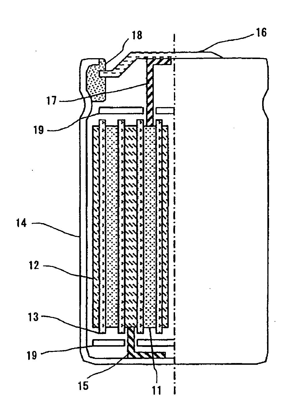
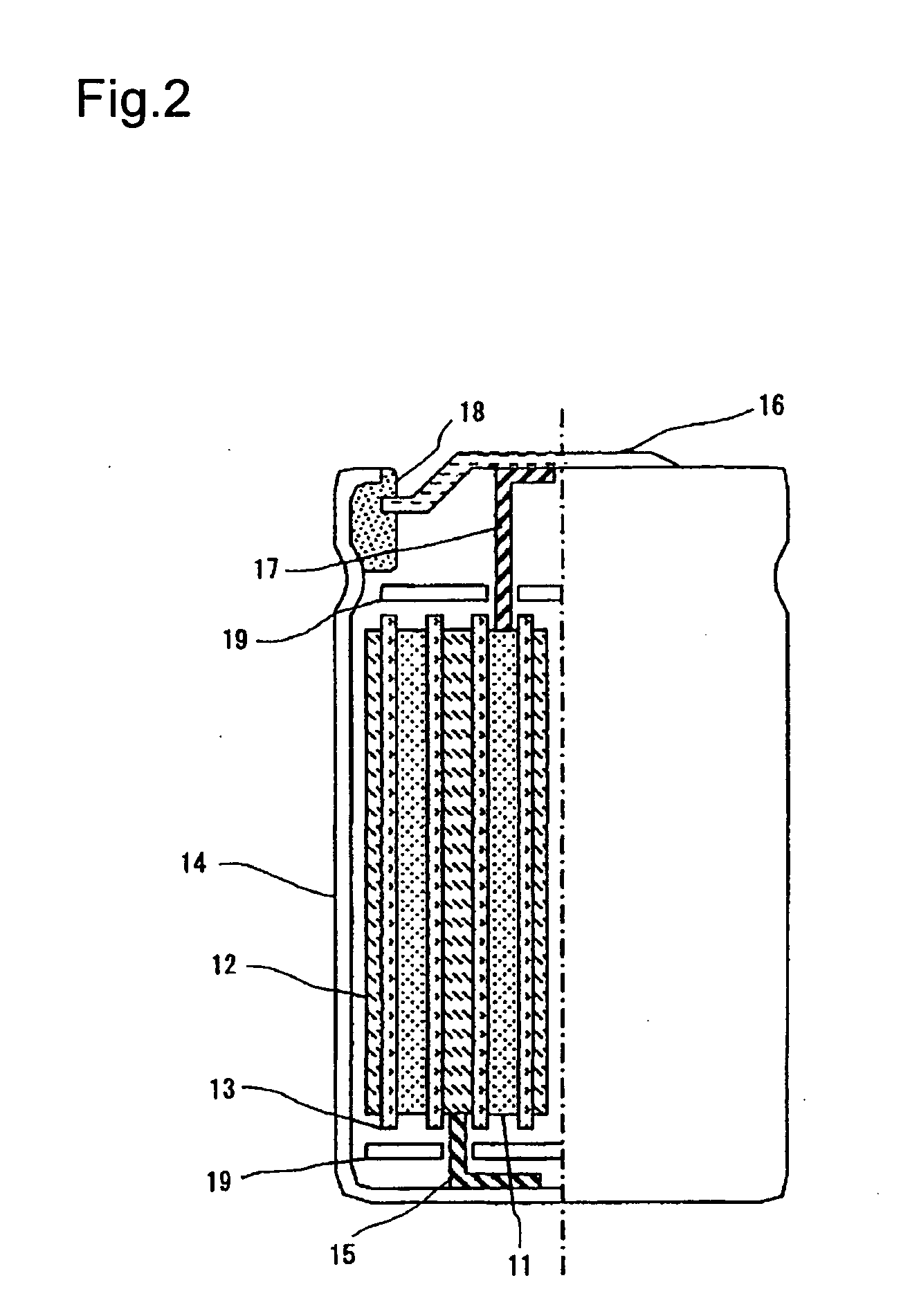
[0063]Subsequently, a negative electrode plate was manufactured to provide a compact cylindrical battery (as shown in FIG. 2) by assembling the positive and negative electrode plates. Pseudo isotropic carbon (hereinafter, referred to as PIC) corresponding to amorphous carbon of a negative electrode material was dissolved into an aggregating agent, NMP, to provide negative electrode mixture slurry. In this case, a dried weight ratio between the PIC and the aggregating agent was set to 92:8. Th...

example 3

[0067]In Example 3, manganese dioxide, cobalt oxide, and nickel oxide, and lithium carbonate were used as a source material. Materials were weighed such that the atomic ratio of Ni:Mn:Co is set to 0.6:0.2:0.2, and the atomic ratio of Li:(NiMnCo) is set to 1.03:1, and then, pure water was added. Using a pot made of resin and a ball mill made of a zirconia ball, the materials are pulverized and mixed in a wet environment so that the particle diameter is reduced to a submicron scale. A polyvinyl alcohol (PVA) liquid is added to a mixture with a solid content ratio of 0.2 wt. %, mixed again for an hour, and granulated and dried using a spray drier, so that particles having a diameter of 5 to 100 μm were produced. Subsequently, these particles were baked at a temperature of 1000° C. for twenty to fifty hours so as to have a layered crystal structure, and then decomposed to provide a positive electrode active material. Bulky particles having a diameter of 50 μm or more are removed from th...


PUM

PropertyMeasurementUnit
diameteraaaaaaaaaa
particle diameteraaaaaaaaaa
lengthaaaaaaaaaa

Abstract

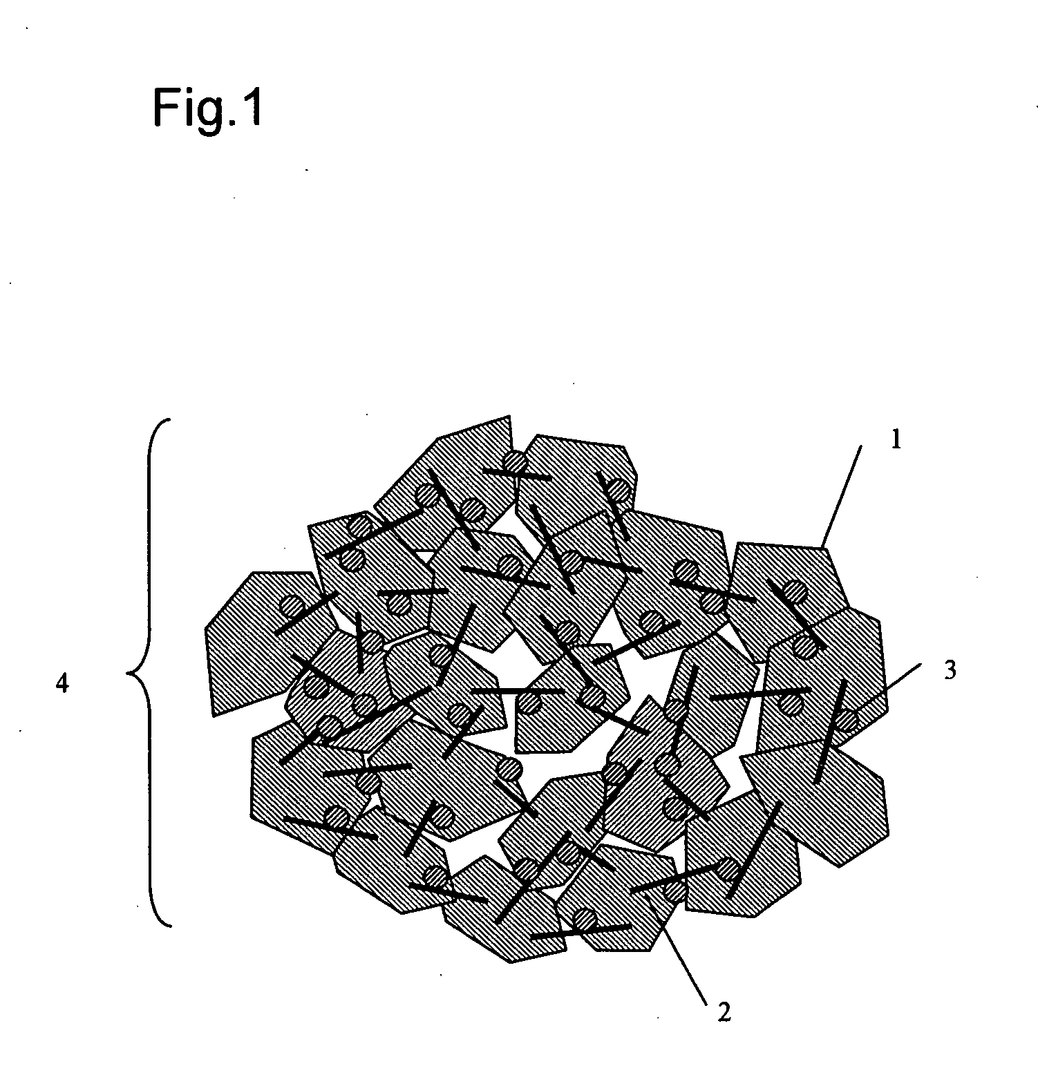
A positive electrode material for a lithium secondary battery according to the invention includes a positive electrode active material containing lithium oxide and a carbon composite obtained by dispersing carbon fiber and a clamped shape carbon material, and the positive electrode active material is combined with the carbon composite. In the positive electrode material for a lithium secondary battery constructed as described above, a conductive network between primary particles is formed by the carbon composite while the positive electrode active material (primary particles) are condensed to form secondary particles.

Description

BACKGROUND OF THE INVENTION[0001]1. Field of the Invention[0002]The present invention relates to a novel positive electrode material for a lithium secondary battery, a novel positive electrode plate for a lithium secondary battery, and a lithium secondary battery using the same, and more particularly, to a positive electrode material used in a large-size lithium secondary battery containing nonaqueous electrolyte and a lithium secondary battery using the same.[0003]2. Background Art[0004]As a power supply for a hybrid vehicle capable of efficiently using energy, a battery having high output power and high energy density is demanded in the art. Since a lithium secondary battery has a high voltage level and a light weight and stores high energy density, it is prospectively used as, for example, a hybrid vehicle battery. In the hybrid vehicle secondary battery, the energy is regenerated and stored when the vehicle is decelerated, and then, high-rate discharge is necessarily performed f...

Claims


Application Information

Patent Timeline
Patent Type & Authority Applications(United States)
IPC IPC(8): H01M4/583H01M4/90B82Y99/00H01M4/02H01M4/131H01M4/36H01M4/505H01M4/525H01M4/62H01M10/05H01M10/052
CPCC01G53/50C01P2006/40H01M4/0404H01M4/1391H01M4/362H01M4/505Y02T10/7011H01M4/625H01M10/052H01M10/0566H01M2004/021H01M2010/4292Y02E60/122H01M4/525Y02E60/10
Inventor YUASA, TOYOTAKAOGAWA, SAITAKAHASHI, HIROFUMI
Owner HITACHI LTD
Learn More