
Bandwidth allocation and management system for cellular networks

Inactive Publication Date: 2010-10-21
TREX ENTERPRISES CORP
View PDF32 Cites 76 Cited by
  • Summary
  • Abstract
  • Description
  • Claims
  • Application Information

AI Technical Summary

Benefits of technology

[0028]The master optical switching and processing station is equipped with a bank of service modules similar to the service modules in the aggregating base stations. Optical signal switching at the master optical switching and processing station is via all optical switches. This master station is equipped with a master controller in control of all of the service modules in the aggregation base stations and the service modules in the master station. The master controller at the master station is able to efficiently utilize all of the service modules in the system so that in the event the service modules in one or more aggregation base stations are on the verge of becoming over-loaded with processing of digital-baseband signal, the master system controller can transfer service functions from those service modules to the service modules in the master optical switching and processing station or to service modules in other aggregation base stations.
[0029]Traditionally, in cellular network, most of the processing of the signals is performed by equipment installed at each base station. This traditional method of processing signals at each base station requires that each base station be equipped with capability to handle its worse case load. However, this capability to handle worse case load is utilized by base stations only rarely. In the methods outlined here, instead of performing all typical functions such as baseband processing, multiple-access control at each base station, baseband signals from a number of auxiliary base stations are digitized and transported to aggregation base station where they are processed. By processing signals from large number of base station using a pool of resources, service module can take advantage of the averaging effect of load distribution among multiple base stations. For example, if no more that 5 out of the 19 base stations are expected to experience peak utilization while the remaining 14 experience half their peak load, the processing capability of service module needs to be no more than capability to handle 12 base stations at peak load, achieving about 30% efficiency, which can translate to 30% of cost saving. This efficiency is improved even further by making use of Master Optical Switching and Processing Stations, which allows averaging among a much larger number of base stations by aggregating and processing of signal from hundreds or thousands of base station. With the cost of base station reaching an upward of $200K and with each operator requiring hundreds of base stations per metropolitan area to serve its customers, the cost saving realized by the proposed method is expected to be enormous. Equally importantly, the operational expenses reduction realized due to the fewer number of equipment needed to be managed are also expected be significant.

Problems solved by technology

However, the construction of fiber optic trunk lines is expensive (sometimes very expensive) and the design and the construction of these lines can often take many months especially if the route is over private property or produces environmental controversy.
Often the expected revenue from the potential users of a particular trunk line under consideration does not justify the cost of the fiber optic trunk line.
In conjunction with the above availability requirements, weather-related attenuation limits the useful range of wireless data transmission at all wavelengths shorter than the very long radio waves.
At the higher, millimeter-wave frequencies, (i.e., 30 GHz to 300 GHz corresponding to wavelengths of 1.0 centimeter to 1.0 millimeter) where available bandwidth is highest, rain attenuation in very bad weather limits reliable wireless link performance to distances of 1 mile or less.
People in the past have avoided use of their cellular equipment because the cost was higher that their line telephones.
Reuse of frequency enables greater spectral efficiency of the system, but is limited by the need to prevent interference.
None of these systems, however, enables optimal sharing of frequency from neighboring cell sites through a centralized control system.
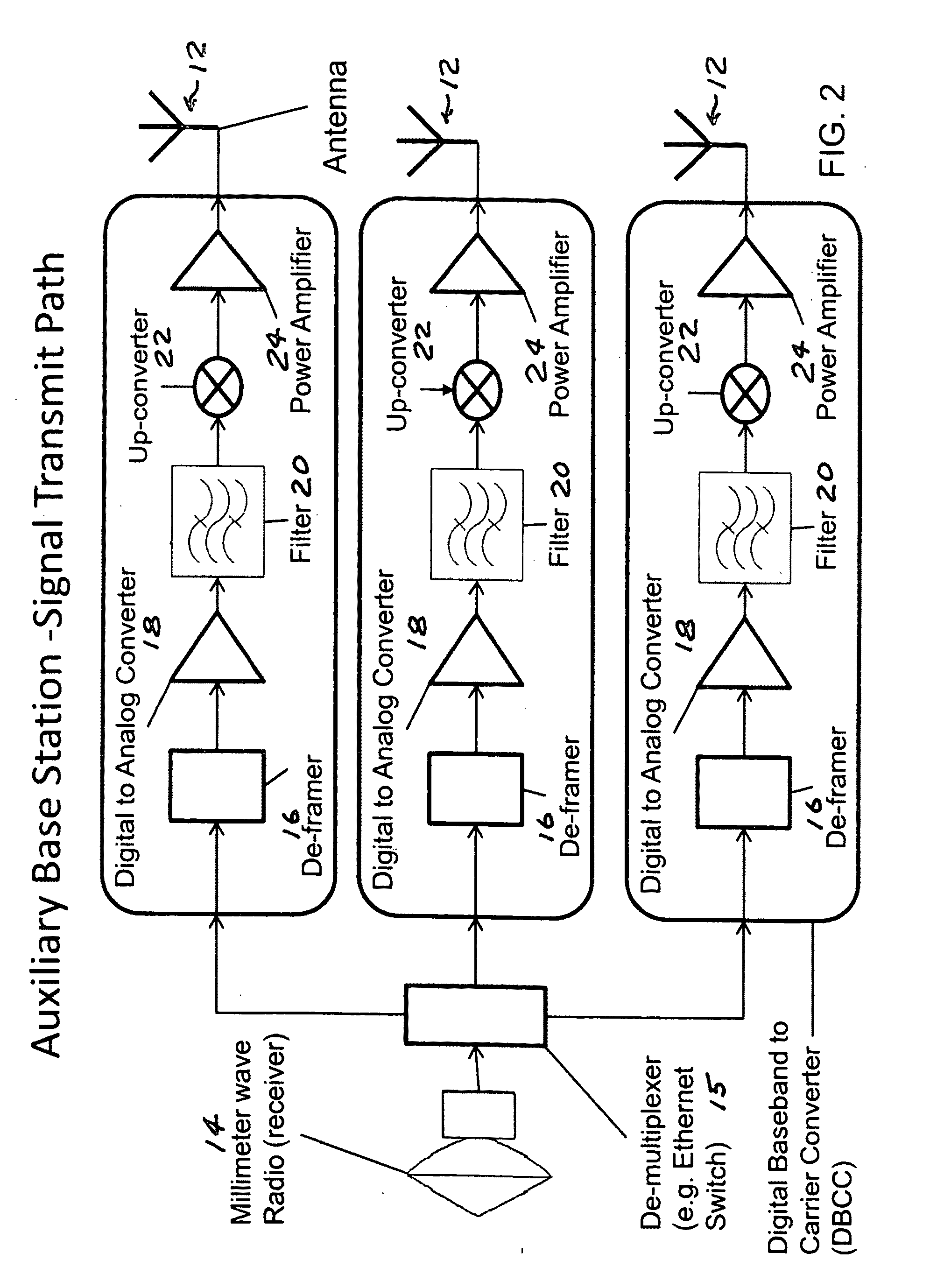
The equipment in these remote cellular stations may be limited to an antenna for low frequency communication with user cellular equipment such as cell phones and other electronic communication equipment including PDA's and laptop computers and equipment for conversion of low frequency cellular signals typically in the range of 800 to 2000 megahertz into a high data rate signal which is transmitted to the supporting base station via the optical fiber or the coaxial cable.
A typical cell site approaches the size of a trailer, has several hundred thousand dollars of equipment, and prodigious power and telecom requirements.
It often is not feasible or prudent to locate these everywhere where a cell site is required.
All equipment needs to be located very close to the antennas on a tower because of transmission losses.
RF signal losses can be significant in a traditional cell site, with 50% or more power lost through cables and a resultant increase in electrical costs.
Third generation services demand more sites because of saturating a maximum aggregate data rate of a cell site, and distance limitations of these services.
The case for cellular operators to migrate to a distributed antenna architecture system is strong, but the mechanism isn't in place in all markets.
However, new site density requirements may mean that a square km in an urban area may require more than a dozen remote sites.
As a result, available fiber with gigabit per second capability is often not available.
The cost of new fiber is typically very high.

Method used


Image

  • Bandwidth allocation and management system for cellular networks
  • Bandwidth allocation and management system for cellular networks
  • Bandwidth allocation and management system for cellular networks

Examples


first preferred embodiment

General Layout

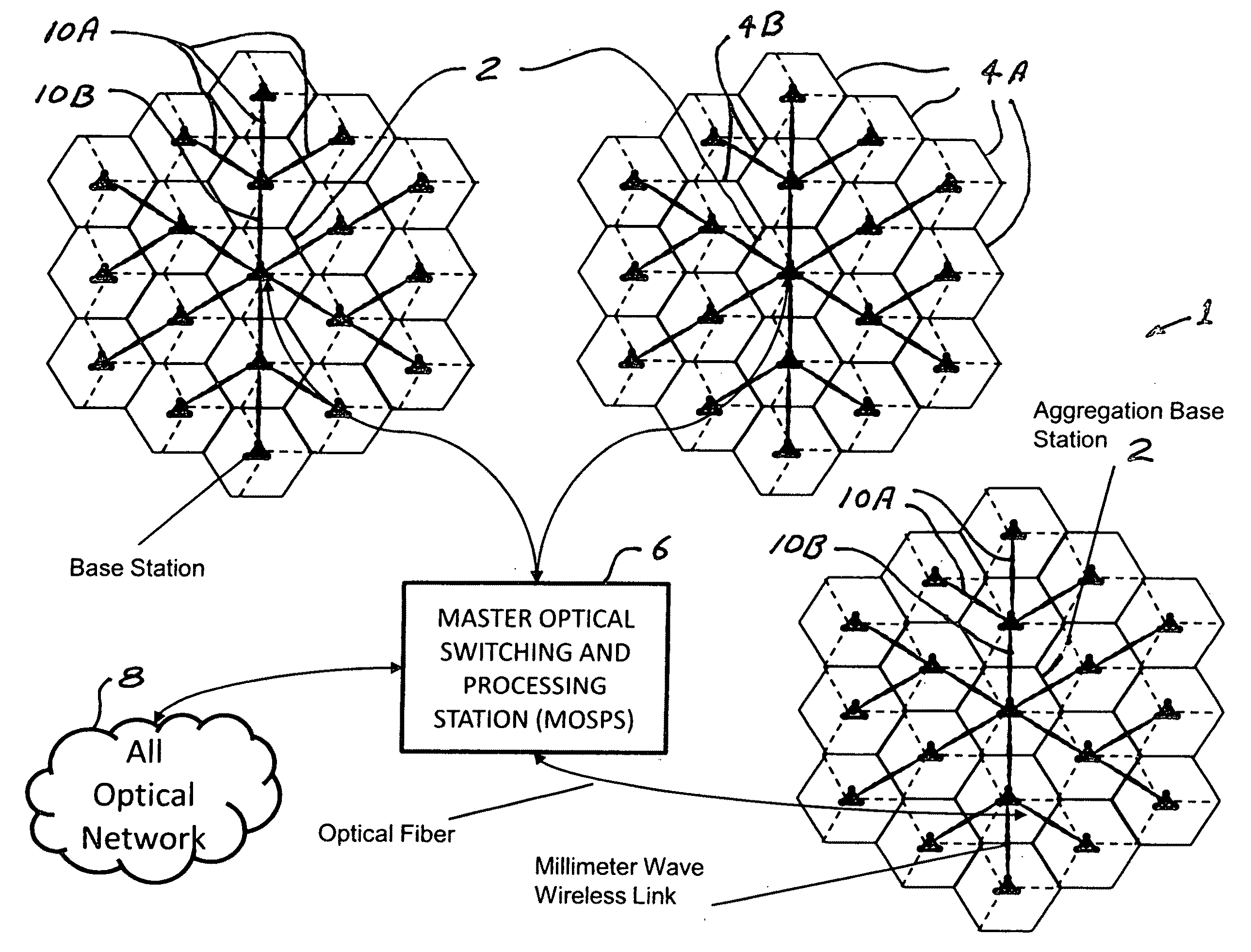
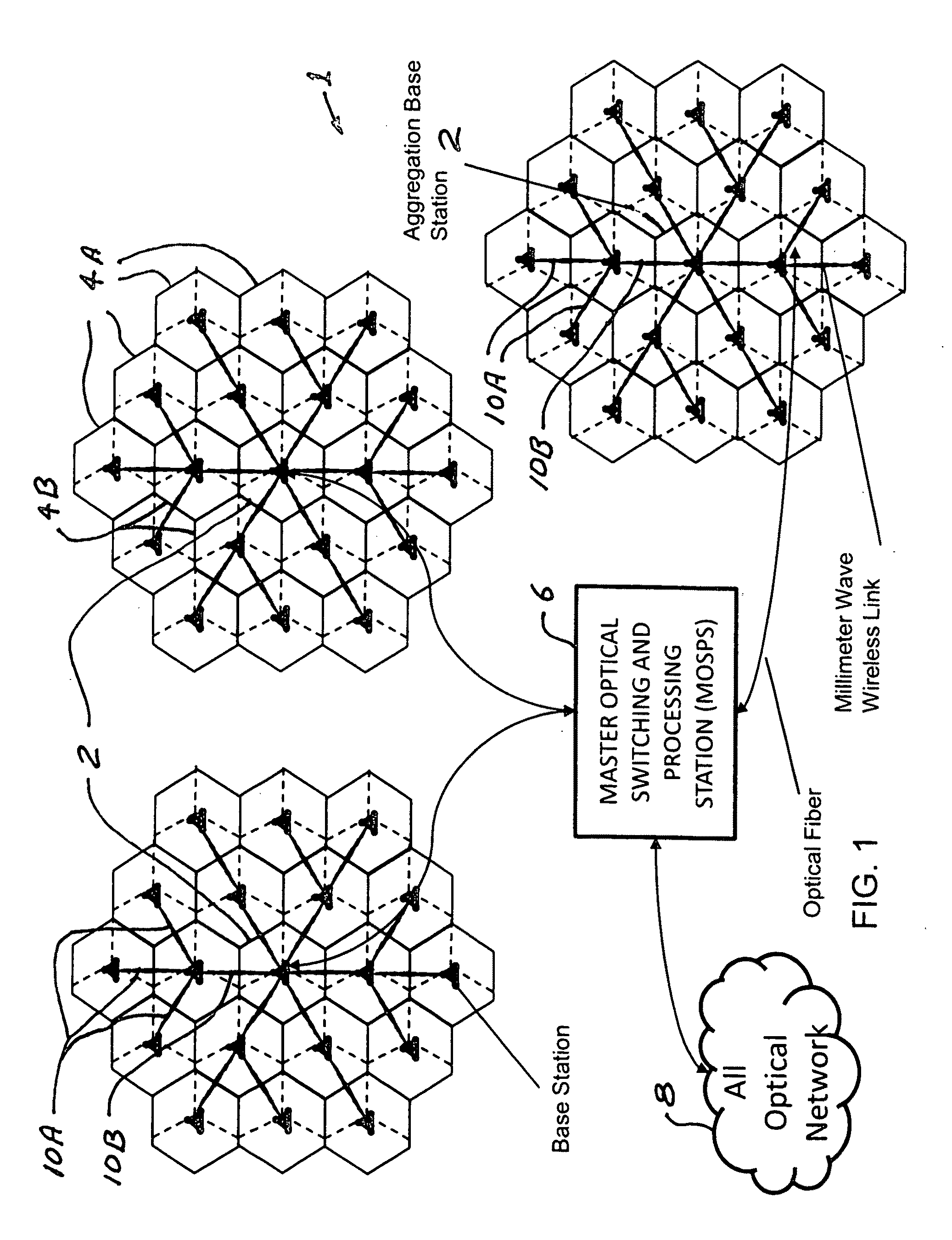
[0051]A first preferred embodiment of the present invention can be described by reference to FIGS. 1 through 8. FIG. 1 is a layout of a bandwidth allocation and management system for a single cellular network 1. The principal components of the network include a number of aggregation base stations 2. Each aggregation base station 2 is surrounded by a number of auxiliary base stations 4A and auxiliary relay base stations 4B. In the network shown there are three aggregation base stations 2 and each of the aggregation base stations is in communication via millimeter wave radio links with 18 associated auxiliary base stations 4A and 4B. The aggregation base stations are each in fiber optical communication with a master optical switching and processing station 6 which in turn is in fiber optical communication with an all optical network 8.

Millimeter Wave Links

[0052]In this embodiment each of the aggregation base stations are in wireless communication with their associated au...

second preferred embodiment

Enhanced Spectral Efficiencies

Through Communication with Users through Multiple Base Stations

[0059]FIGS. 9 through 21 illustrate a second preferred embodiment in which a key benefit of this architecture can be realized. In traditional cellular network architecture, each cellular base station acts as in independent entity. As illustrated in FIG. 9, located at each base station is a set of antennas that receive and transmit radio signals and a set of processing equipment that process these signals. Even though signals transmitted by a mobile handheld devices propagate omni-directionally and is received by neighboring base stations as shown in FIG. 10, all but one of the base stations discards the signals. Only the base station that receives the strongest signal processes it and extracts information. In the same fashion, only one base station transmits signal to the mobile devices.

[0060]By harnessing the signal received by all the neighboring base stations, the system can achieve highe...


PUM


Abstract

A bandwidth allocation and management system for cellular communication networks. The system includes at least one master optical switch and processing station, a number of aggregation base stations that are in optical fiber communication with a master optical switching and processing station and a number of auxiliary cellular base stations surrounded by and supported by each aggregation base station. In preferred embodiments a plurality of sets of three neighboring base stations are each adapted to receive and process RF signals transmitted by cellular users within a broadcast and receive range and transmit the RF signals received, by each of the three neighborhood base stations, from each of the cellular users in analog form to the master optical switching and processing station. The master optical switching and processing station processes the three RF signals and combine, for each user within the broadcast and receive range, the three RF signals and to convert the combined RF signals to digital form for transmission to other users in the communication network.

Description

CROSS REFERENCE TO RELATED APPLICATIONS[0001]This application claims the benefit of provision patent application Ser. No. 61 / 212,814 filed Apr. 16, 2009 and is a continuation-in-part application of Ser. No. 12 / 592,238, filed Nov. 21, 2009, each of which are incorporated herein by reference.FIELD OF THE INVENTION[0002]The present invention relates to cellular communication systems and in particular to high data rate cellular communication systems.BACKGROUND OF THE INVENTIONLocal Wireless Radio CommunicationWiFi and WiMax[0003]Local wireless communication services represent a very rapidly growing industry. These services include paging and cellular telephone services and wireless internet services such as WiFi and WiMax. WiFi refers to communication systems designed for operation in accordance with IEEE 802.11 standards and WiMax refers to systems designed to operate in accordance with IEEE 802.16 standards. Communication under these standards is typically in unlicensed portions of th...

Claims


Application Information

Patent Timeline
IPC IPC(8): H04B10/00H04M1/00
CPCH04W88/085H04W72/0453
Inventor ADHIKARI, PRASANNATIGLI, HUSFEIN, ROBERT A.
Owner TREX ENTERPRISES CORP
Learn More