Systems and methods for the separation of carbon dioxide and water

a technology applied in the field of carbon dioxide and water separation systems, can solve the problems of high purity, difficult separation, and inability to meet the requirements of high purity, and achieve the effect of improving the separation efficiency and reducing the cost of solvents

Inactive Publication Date: 2010-11-04
MASSACHUSETTS INST OF TECH
View PDF69 Cites 47 Cited by
  • Summary
  • Abstract
  • Description
  • Claims
  • Application Information

AI Technical Summary

Benefits of technology

[0010]Other advantages and novel features of the present invention will become apparent from the following detailed description of various non-limiting embodiments of the invention when considered in conjunction with the accompanying figures. In cases where the present specification and a document incorporated by reference include conflicting and / or inconsistent disclosure, the present specification shall control. If two or more documents incorporated by reference include conflicting and / or inconsistent disclosure with respect to each other, then the document having the later effective date shall control.

Problems solved by technology

In order to effectively and safely sequester carbon dioxide by many current and proposed techniques, however, relatively high purities are required.
However, these techniques may pose disadvantages.
For example, organic solvent-based methods often make use of expensive and / or toxic solvents.
In addition, many of the above-mentioned methods require use of expensive, specialized equipment and / or are energy intensive, leading to large parasitic loads on power generating systems to which they are applied.

Method used


Image

  • Systems and methods for the separation of carbon dioxide and water
  • Systems and methods for the separation of carbon dioxide and water
  • Systems and methods for the separation of carbon dioxide and water

Examples


example 1

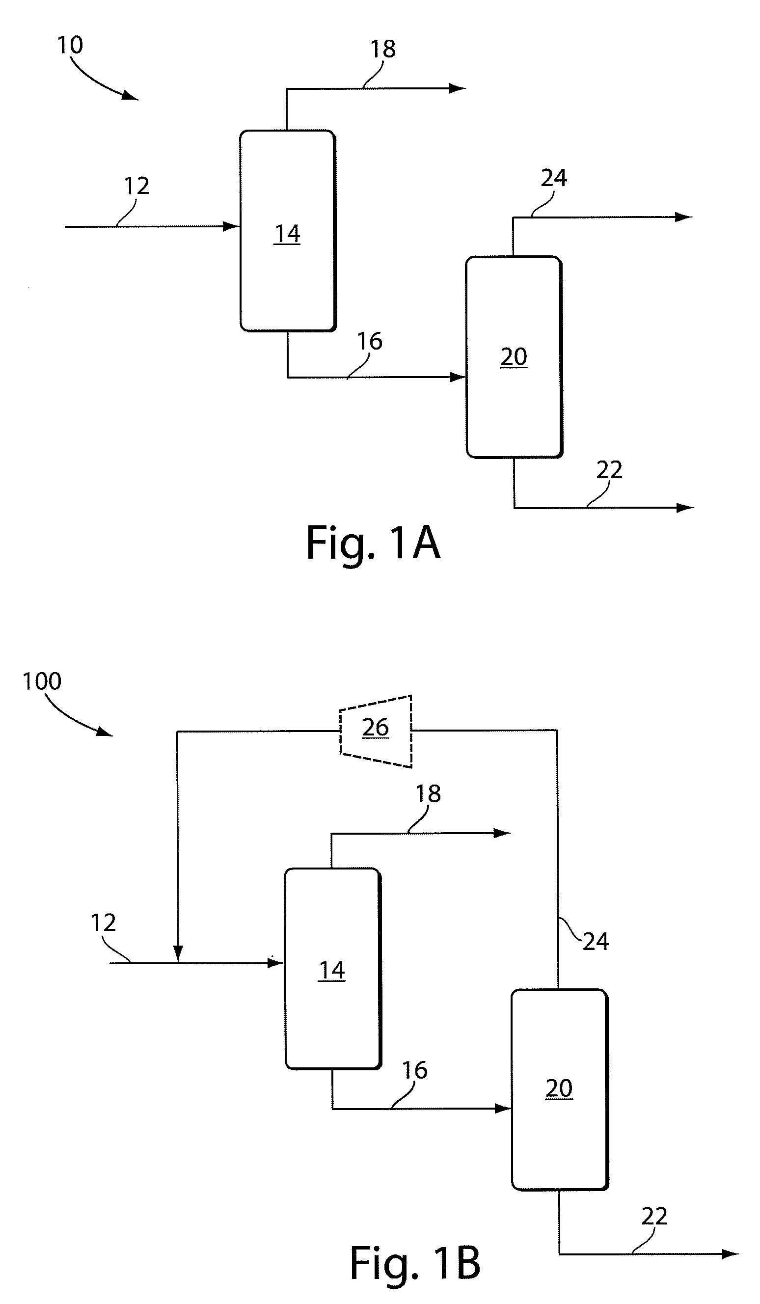
[0089]This example describes a process simulation of a two-stage flash separation of carbon dioxide and water. The feed stream compositions and conditions listed in all examples herein were calculated using Aspen Plus 2006.5. All simulations described herein used the Peng-Robinson equation of state with the Boston-Mathias modification on all process units, except: Redlich-Kwong-Soave EOS with predictive Holderbaum mixing rules for streams primarily containing CO2 and H2O well below the critical point of CO2; NBC / NRC steam tables were used for pure water streams; and the electrolyte-NRTL model with Henry coefficients and electrolyte chemistry specifications obtained from the AP065 databank for CO2 / H2O rich streams near the critical pressure of CO2. All compressors and turbines were assumed to have an isentropic efficiency of 0.72, a mechanical efficiency of 1, and a maximum pressure ratio of 5.0. All pump efficiencies were calculated according to the software's default method, which ...

example 2

[0093]This example describes a process simulation of a process for the four-stage flash separation of carbon dioxide and water. The feed stream compositions and conditions listed in this example were calculated using Aspen Plus 2006.5 as described in Example 1. FIG. 8 is a schematic diagram of the four-stage flash system 800. The stream compositions and conditions in FIG. 8 are outlined in Table 2 below.

TABLE 2Stream compositions and conditions for the four-stage flash separation systemin FIG. 8Stream12.112.212.312.412.512.6T (° C.)1052121212121P (bar)18.618.518.418.415.015.0F (kmol / h)281192827712224160532416029Vapor Frac.0.466250.432281010MoleH2O56.58%56.27%0.17%98.99%0.2%99.14%FractionsN20.76%0.75%1.75%3 ppm0.17%212ppbAr0.69%0.68%1.58%7 ppm0.36%1ppmCO692 ppb688 ppb2 ppm315 ppbCO241.97%42.28%96.49%1.01%99.26%0.86%Stream12.712.812.912.1012.1112.12T (° C.)2020502121246P (bar)4.04.01.11.11.118.5F (kmol / h)10015929158953535158Vapor Frac.100111MoleH2O 0.6%99.76%99.97%2.24%2.24% 0.9%Fract...

example 3

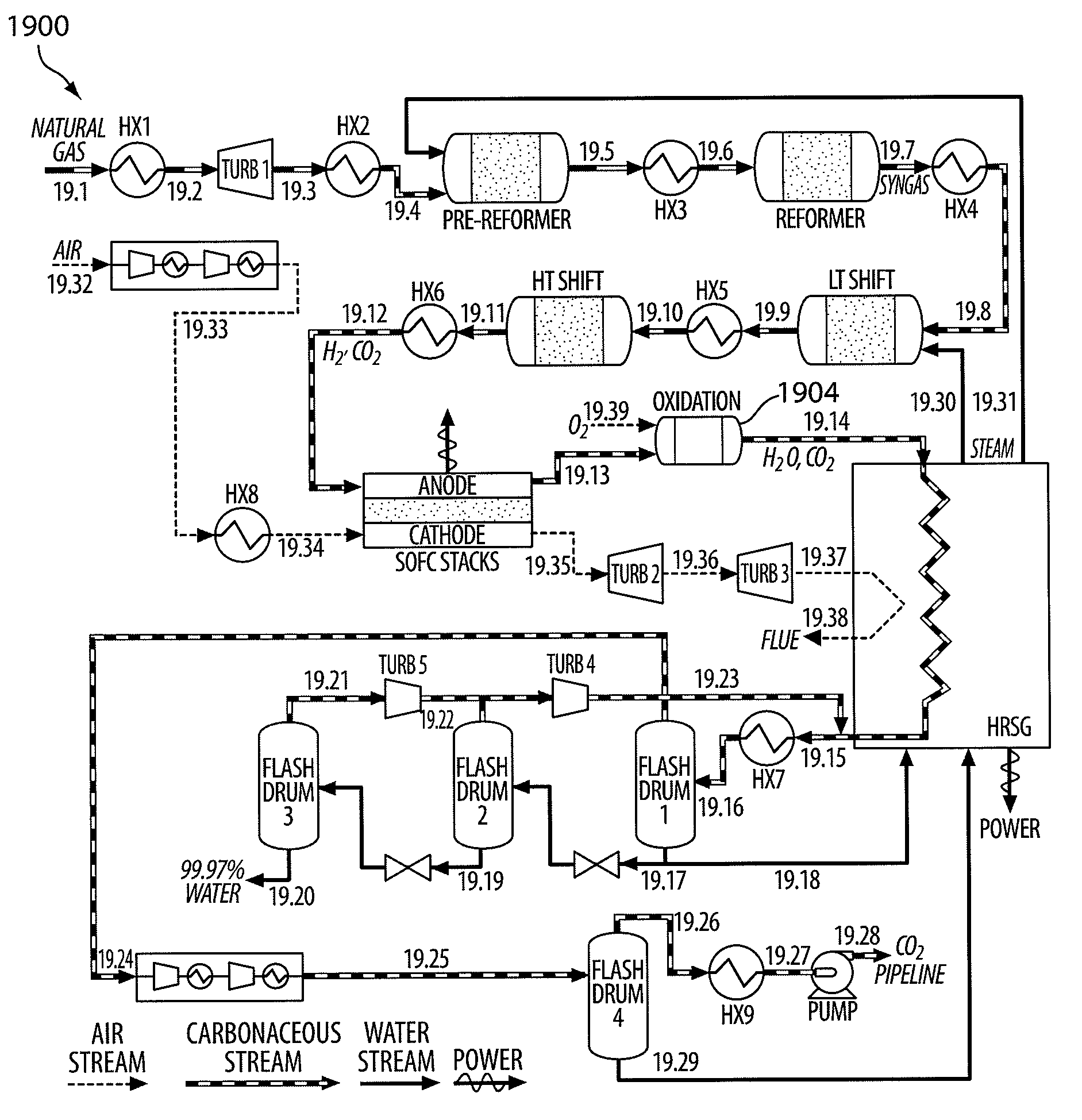
[0098]This example describes a process simulation of a process for power and water production from coal with carbon capture and sequestration. The feed stream compositions and conditions listed in this example were calculated using Aspen Plus 2006.5 using the same physical property models and assumptions described in Example 1.

[0099]FIG. 9 is a schematic diagram of the integrated gasification / fuel cell / CO2—H2O separation system 900 described in this example. The amount of high-purity water generated in the system is sufficient to meet the fresh water consumption needs of the system, and the system as a whole operates at a higher efficiency compared to conventional processes with coal feeds.

[0100]To begin, ambient air is fed to an air separation unit (1 ASU), where the oxygen and nitrogen in the air are separated. Some of the O2 is compressed to high pressure and fed to the gasifier (2 Gasifier), and the rest is compressed to medium pressure and sent to the sulfur collection unit (10...


PUM

PropertyMeasurementUnit
wt %aaaaaaaaaa
electrical poweraaaaaaaaaa
temperatureaaaaaaaaaa

Abstract

Systems and methods for the separation and capture of carbon dioxide from water are generally described. In some embodiments, a vapor stream containing carbon dioxide and water is separated using a cascade of at least two flash drums. Additional flash steps may be incorporated to remove atmospheric gases, such as nitrogen and argon, from the feed. Carbon dioxide may be condensed and pressurized at purities suitable for pipeline transport and eventual storage in geological formations. In addition, water may be recovered at high purity.
In some embodiments, fuel cells may be used in combination with fuel reforming or gasification to produce syngas. Certain aspects of the invention involve innovations related to the combined reforming and fuel cell process, that, in certain embodiments, do not depend upon water and carbon dioxide separation. It should be understood, however, that the invention is not limited to the applications described above, and may be used with any suitable system in which the separation of carbon dioxide and water is desired.

Description

FIELD OF INVENTION[0001]Systems and methods for the separation of carbon dioxide and water are generally described, which are particularly suited, in certain embodiments for use in power generation systems.BACKGROUND[0002]Carbon dioxide and water vapor are commonly found in the exhaust emitted from many industrial processes such as fossil fuel power plants, including those using conventional pulverized coal, integrated gasification combined cycles (IGCC), natural gas combined cycles, chemical looping, and fossil oil-based fuels. Currently, these gases are typically simply vented to the atmosphere. However, due to recent widespread environmental concern and developing and expected regulatory mandates, it is desirable to minimize atmospheric carbon dioxide emissions.[0003]One proposed method of reducing carbon dioxide emissions involves carbon dioxide capture and, optionally, sequestration. In order to effectively and safely sequester carbon dioxide by many current and proposed techni...

Claims


Application Information

Patent Timeline
Patent Type & Authority Applications(United States)
IPC IPC(8): H01M8/04H01M8/18C02F1/06C01B32/50
CPCB01D53/265B01D2257/2045B01D2257/602Y02E60/50H01M8/04164H01M8/0612H01M8/0668B01D2257/80
Inventor ADAMS, II, THOMAS ALANBARTON, PAUL INIGO
Owner MASSACHUSETTS INST OF TECH
Why Eureka
Try Eureka