

Organic electroluminescent element
- Summary
- Abstract
- Description
- Claims
- Application Information
AI Technical Summary
Benefits of technology
Problems solved by technology
Method used
Image

Examples
embodiment 1
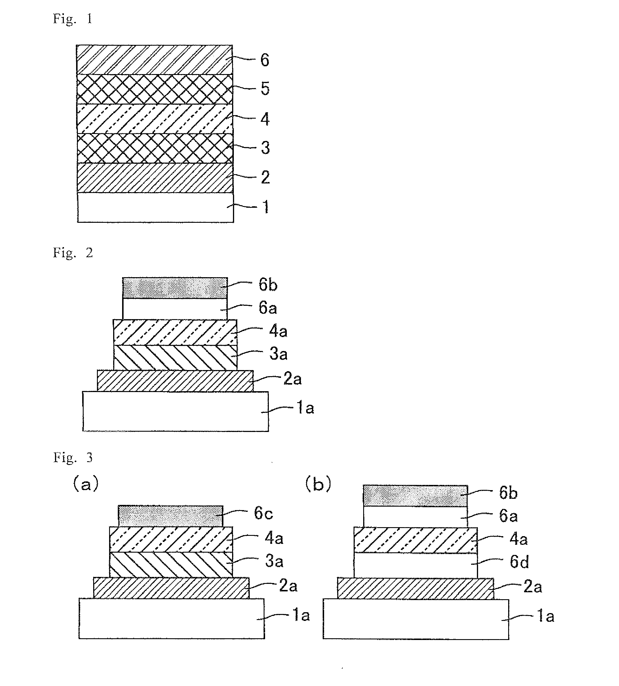
[0062]FIG. 1 is a schematic cross-sectional view of an organic EL element of Embodiment 1. The organic EL element of the present embodiment has a structure where a first electrode 2, a first nanoparticle layer 3, a light-emitting layer (organic light-emitting layer) 4, a second nanoparticle layer 5, and a second electrode 6 are stacked on a substrate 1 in the stated order, as illustrated in FIG. 1. In the following, a production method of the organic EL element of the present embodiment is described.
[0063]As the substrate 1 in the present embodiment, a substrate having an insulating surface is preferable. Examples of such a substrate include substrates made of an inorganic material such as glass and quartz; substrates made of plastic such as polyethylene terephthalate; substrates made of ceramics such as alumina; substrates formed by coating an insulator such as SiO2 or an organic insulating material, on a metal substrate such as aluminum or iron; and substrates formed by performing...
embodiment 2
[0119]The organic EL element of the present embodiment has the same configuration as the organic EL element of Embodiment 1 illustrated in FIG. 1. The only difference between the present embodiment and Embodiment 1 is that the nanoparticle layer 5 is formed on the light-emitting layer 4 by spin coating. The thus-produced organic EL element of the present embodiment is referred to as an element C.
[0120]As described above, in the element C, the nanoparticle layer 5 is intentionally formed by spin coating. The solution for nanoparticle layer 5 formation is the same as the solution used in Embodiment 1. The solvent of this solution contains xylene which dissolves the light-emitting layer 4. Since the solution is applied on the light-emitting layer 4 by spin coating in the present embodiment, the upper surface (the surface on the opposite side of the substrate 1) of the light-emitting layer 4 dissolves unlike in the case of being formed by spraying as in Embodiment 1. As a result, the fa...
embodiment 3
[0124]The organic EL element of the present embodiment has the same configuration as the organic EL element of Embodiment 1 illustrated in FIG. 1. The only difference between the present embodiment and Embodiment 1 is that the metal oxide nanoparticles are dispersed in the light-emitting layer 4. The thus-produced organic EL element of the present embodiment is referred to as an element D.
[0125]The material of the metal oxide nanoparticles dispersed in the light-emitting layer 4 is barium titanate as in Embodiment 1, and the weight percentage of these metal oxide nanoparticles to the light-emitting material in the light-emitting layer 4 is controlled to be 25%. The average particle diameter of these metal oxide nanoparticles is 20 nm.
[0126]The light-emitting material B, which is a material of the same kind as the light-emitting material A, is used as the light-emitting material. According to the evaluation by a single carrier device, the light-emitting material B has an electron tra...
PUM
 Abstract
Description
Claims
Application Information