

Inter-organ spacer for use in endoscopic surgery
a technology for endoscopic surgery and interorgan spacers, which is applied in the field of interorgan spacers for use in endoscopic surgery, can solve the problems of degrading the endoscopic field, affecting the quality of endoscopic surgery, so as to reduce the risk of damage, and reduce the force
- Summary
- Abstract
- Description
- Claims
- Application Information
AI Technical Summary
Benefits of technology
Problems solved by technology
Method used
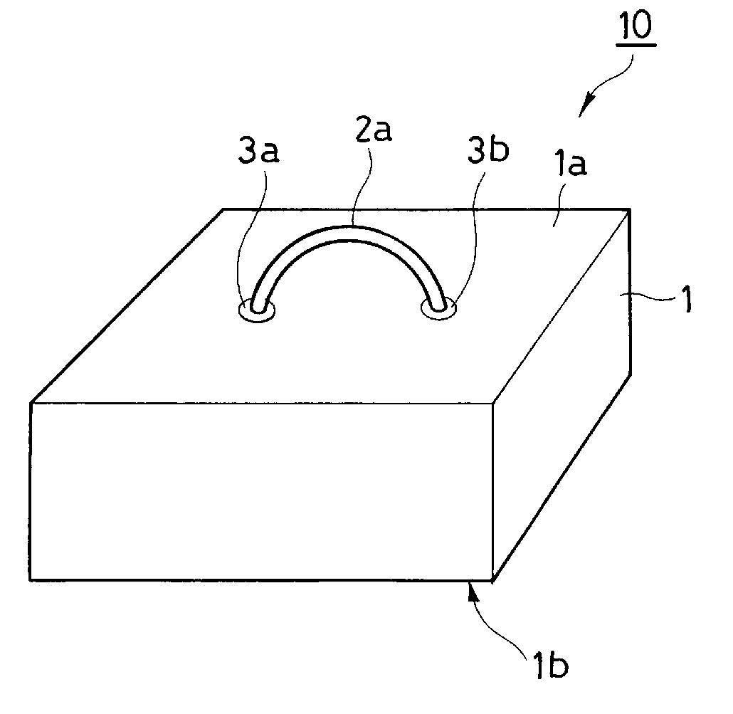
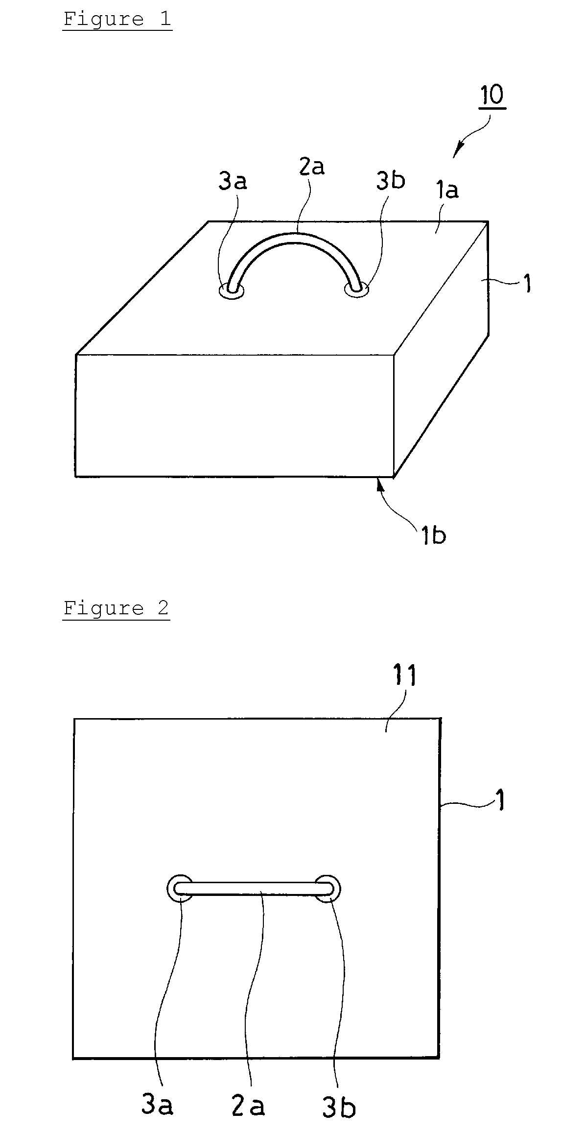
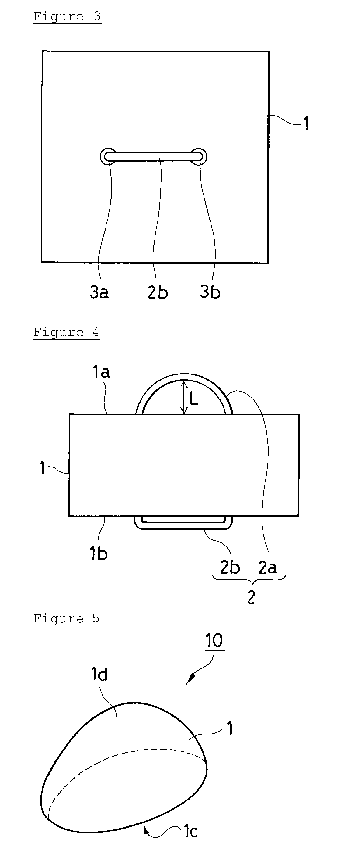
Image

Examples
example 1
Evaluation of Liquid Absorbency
[0091]This example and each example described below were performed using three porous soft materials (hereinafter referred to as sample set A): a polyurethane material with low liquid releasing ability (Toughponge (Hogy Medical Co., Ltd.)); a polyurethane material with high liquid releasing ability for abdominal surgery; and a polyvinyl alcohol material (Retractor Pad (Heiwa Iryo Kikai Co., Ltd.)). Another sample set used includes six materials (hereinafter referred to as sample set B): the polyurethane material with low liquid release ability (Toughponge (Hogy Medical Co., Ltd.), hereinafter also referred to as sample A); four different polyurethane materials with high liquid releasing ability (hereinafter also referred to as samples B to E); and a polyethylene material (hereinafter also referred to as sample F). Table 2 shows the principal properties of each porous soft material used in sample sets A and B. The elongation in Table 2 was measured acco...
example 2
Evaluation of Liquid Holding Ability
[0098]The weight (Wd in units of g) of the sample (in the shape of a rectangular parallelepiped of 20 mm×20 mm×80 mm) was measured before it was allowed to absorb artificial blood. After the sample was allowed to absorb a sufficient amount of artificial blood (Synthetic Blood Reagent Mix (Johnson, Moen & Co.)), its weight (Ww in units of g) was measured. Subsequently, the sample was placed on a polyvinyl chloride plate, and the plate was allowed to stand for 3 minutes, while being tilted at 45°. Thereafter, the weight (W3 in units of g) of the sample was measured.
[0099]The liquid holding ability was calculated from the following formula: (W3−Wd)÷(Ww−Wd)×100(%).
[0100]The results on sample sets A and B are shown in Tables 5 and 6, respectively. Three samples were prepared for each material, and the average of the liquid holding abilities (%) of the respective samples was calculated. The higher value indicates the higher liquid holding ability.
TABLE ...
example 3
Evaluation of Liquid Releasing Ability
[0101]The weight (Wd in units of g) of the sample (in the shape of a rectangular parallelepiped of 20 mm×50 mm×50 mm) was measured before it was allowed to absorb artificial blood. After the sample was allowed to absorb a sufficient amount of artificial blood (Synthetic Blood Reagent Mix (Johnson, Moen & Co.)), it was placed on a plastic plate, and its weight (Ww in units of g) was measured. The artificial blood was sucked under a reduced pressure of −600 to −650 mmHg (−80 to −85 kPa) for 1 minute, while the tip of a Yanker suction tube was held to the center of the sample and pushed in. After the suction, the weight (Ws in units of g) of the sample being placed on the plastic plate was measured. The liquid releasing ability was calculated from the following formula: (Ww−Ws)÷(Ww−Wd)×100(%).
[0102]The results on sample sets A and B are shown in Tables 7 and 8, respectively. Three samples were prepared for each material, and the average of the liqu...
PUM
 Abstract
Description
Claims
Application Information