
Composite structures for high energy-density capacitors and other devices

a technology of high energy density and capacitors, applied in the direction of fixed capacitor details, cellulosic plastic layered products, fixed capacitors, etc., can solve the problems of composite material brittleness, device breakdown strength and mechanical properties, processing and fabrication problems,

Inactive Publication Date: 2010-12-02
GENERAL ELECTRIC CO
View PDF16 Cites 31 Cited by
  • Summary
  • Abstract
  • Description
  • Claims
  • Application Information

AI Technical Summary

Benefits of technology

[0004]Over the last decade, significant increases in capacitor reliability have been achieved through a combination of advanced manufacturing techniques and new materials. In addition, polymer-based electronic devices, such as a capacitor, would offer compact capacitor structure, self-clearing capability, longer lifetime, and higher energy density. These advantages, coupled with the advantage of reduced size, simplicity, and cost of manufacturing, enable the wide use of these polymer based capacitors in the power electronics industry.

Problems solved by technology

The disadvantage, however, is that some of these devices might exhibit an undesirable reduction in breakdown strength and mechanical properties, such as impact strength and ductility.
Moreover, the addition of fillers increases the brittleness of the composite material, thereby giving rise to processing and fabrication problems.
However, most of the dielectric polymers are characterized by low energy densities (<5 J / cc), and / or have low breakdown strengths (<450 kV / mm), which may limit the operating voltage of the capacitor.
Other disadvantages are sometimes associated with these types of capacitors as well, relating to thermal stability and reduced lifetime, for example.
A trade-off between these two properties may not be advantageous.

Method used


Image

  • Composite structures for high energy-density capacitors and other devices
  • Composite structures for high energy-density capacitors and other devices
  • Composite structures for high energy-density capacitors and other devices

Examples


examples

[0042]The following examples illustrate methods and embodiments in accordance with the invention, and as such, should not be construed as imposing limitations upon the claims.

[0043]Unless specified otherwise, all ingredients may be commercially available from such common chemical suppliers as Alpha Aesar, Inc. (Ward Hill, Mass.), Sigma Aldrich (St. Louis, Mo.), Spectrum Chemical Mfg. Corp. (Gardena, Calif.), and the like.

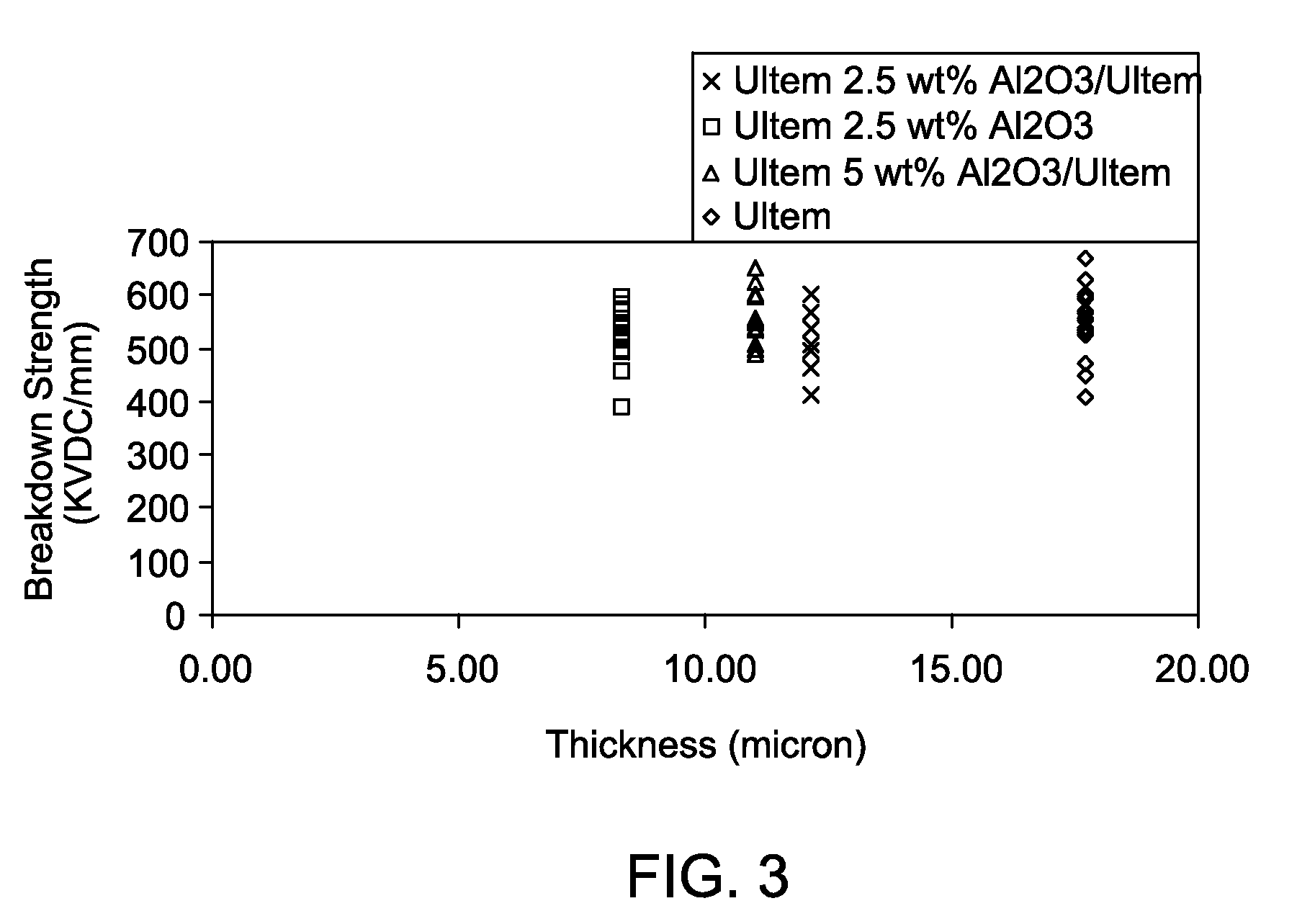
[0044]Alumina particles with an average particle size of 45 nm from Alpha Aesar, Inc were compounded into a cyanoethyl pullulan(CRS™) polymer resin (from Shin-Etsu Chemical Co. Ltd.) at 5 weight percent, based on the total weight of the resin and the alumina, to form the nanocomposite. The cyanoethyl pullulan polymer resin was added to a solvent in an amount of 10 wt %, based on the total weight of the solution of cyanoethyl pullulan polymer resin and the solvent. The solvent used for the solution casting was dimethylformamide (DMF). The nanocomposite was then disso...


PUM

PropertyMeasurementUnit
Mechanical strengthaaaaaaaaaa
Fractionaaaaaaaaaa
Fractionaaaaaaaaaa

Abstract

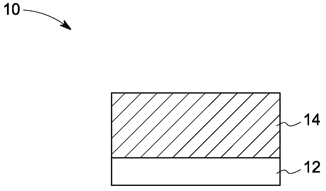
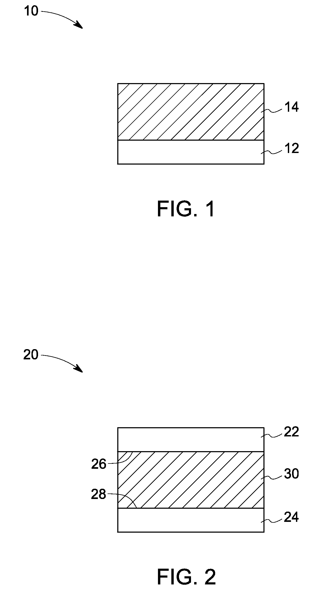
In one aspect of the present invention, an article is described, including a polymer layer; and a composite layer disposed on the polymer layer. The composite layer includes a thermoplastic polymer, which contains at least one inorganic component having selected dimensions; wherein the largest dimension of the inorganic component is less than about 1 micrometer. The composite layer has a dielectric constant, which is at least about 30 percent greater than the dielectric constant of the polymer layer. The article has a breakdown strength of at least about 150 kV / mm. Related devices are also described.

Description

BACKGROUND[0001]The invention relates generally to an article having a high breakdown strength and comprising a composite layer having a high dielectric constant.[0002]Polymers with high resistivity, high permittivity, low dissipation factors and high electric field breakdown strengths (Vb) have important applications as dielectrics in electronic devices, such as a capacitor. The electronic industry is cost- and performance-driven, and constantly increasing demands are made on materials to lower cost, and improve their reliability and performance. Polymer based devices have long been of interest because manufacturing technologies associated with extrusion or solution casting of polymer films can be readily combined with thin film metallization techniques, to yield devices that are flexible and economical, and which can be manufactured into very large electronic devices.[0003]Polymer films such as polycarbonate, polypropylene and polyester have been the insulating media of choice for...

Claims


Application Information

Patent Timeline
IPC IPC(8): H01G4/08B32B5/16B32B7/02B32B27/08B32B23/08
CPCB32B2309/105B32B2457/16H01G4/14H01G4/206Y10T428/31721Y10T428/31971Y10T428/25Y10T428/2495
Inventor TAN, DANIEL QIIRWIN, PATRICIA CHAPMANCAO, YANG
Owner GENERAL ELECTRIC CO
Learn More