Method for creating s/tem sample and sample structure

a technology of transmission electron microscope and sample structure, which is applied in the direction of material analysis using wave/particle radiation, instruments, and therapies, etc., can solve the problems of destroying much affecting the quality of the original sample, and the size of the feature to be measured, so as to increase the throughput and reproducibility of tem analysis, and the process of creating and analysing tem samples is less labor-intensive.

a technology of transmission electron microscope and sample structure, which is applied in the direction of material analysis using wave/particle radiation, instruments, and therapies, etc., can solve the problems of destroying much affecting the quality of the original sample, and the size of the feature to be measured, so as to increase the throughput and reproducibility of tem analysis, and the process of creating and analysing tem samples is less labor-intensive.

US20100308219A1Active Publication Date: 2010-12-09FEI CO

Image

  • Method for creating s/tem sample and sample structure
  • Method for creating s/tem sample and sample structure
  • Method for creating s/tem sample and sample structure

Examples


Embodiment Construction

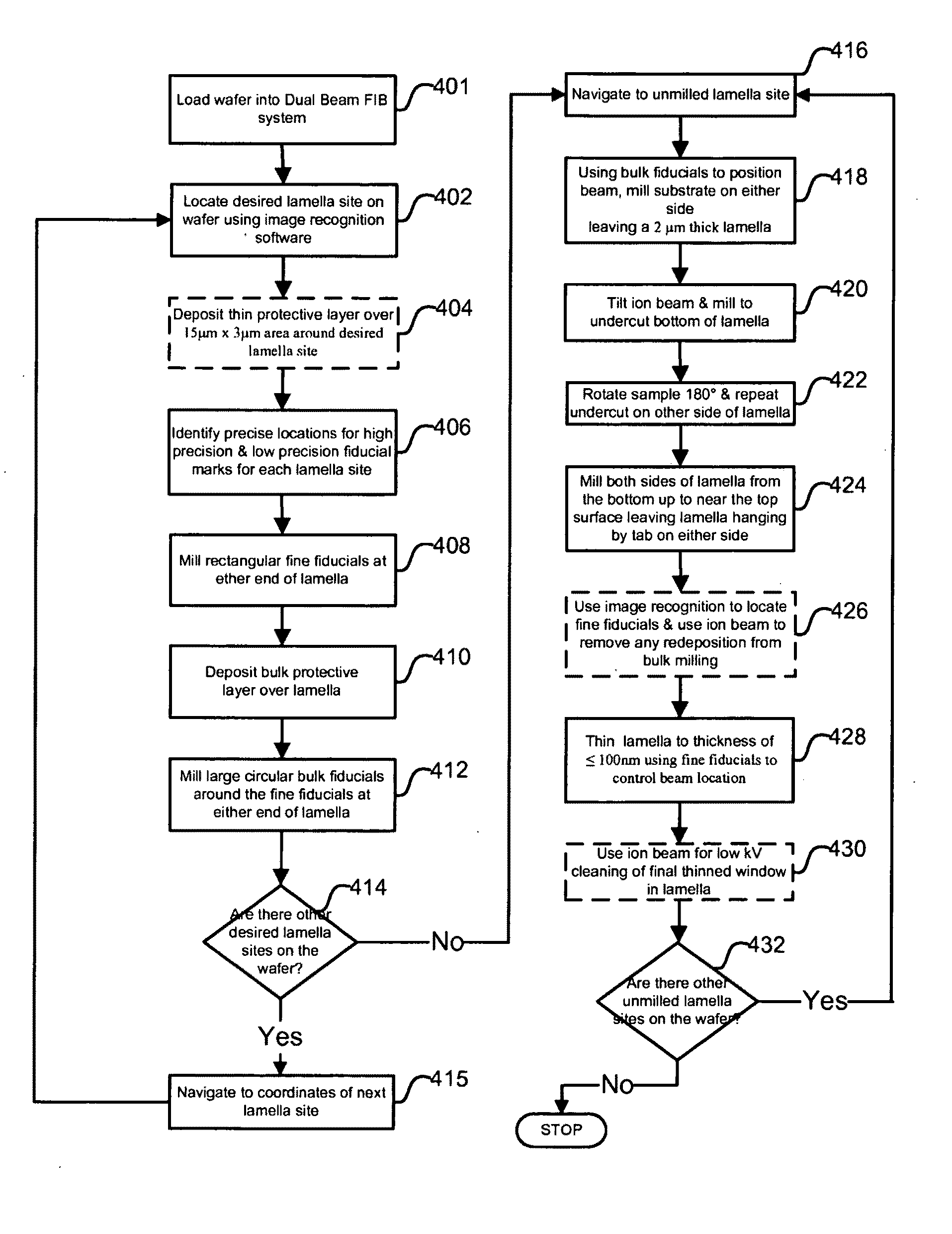
[0041]Preferred embodiments of the present invention provide improved methods for lamella creation. A preferred embodiment can create S / TEM samples with a thickness in the 50-100 nm range for the purposes of S / TEM metrology with minimal site-to-site variation. The process can produce a 10 μm wideט5 μm deepט500 nm thick lamella with a final-thinned window of 3 μm×3 μm at the targeted final thickness (50-100 nm). S / TEM samples produced according to the present invention will not suffer from bowing phenomenon when thinned to 100 nm or less and are robust enough to survive automated extraction and mounting.

[0042]A preferred method or apparatus of the present invention has many novel aspects, and because the invention can be embodied in different methods or apparatuses for different purposes, not every aspect need be present in every embodiment. Moreover, many of the aspects of the described embodiments may be separately patentable.

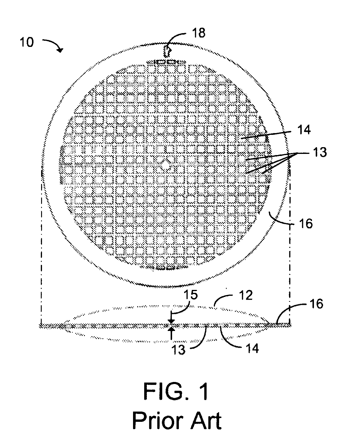
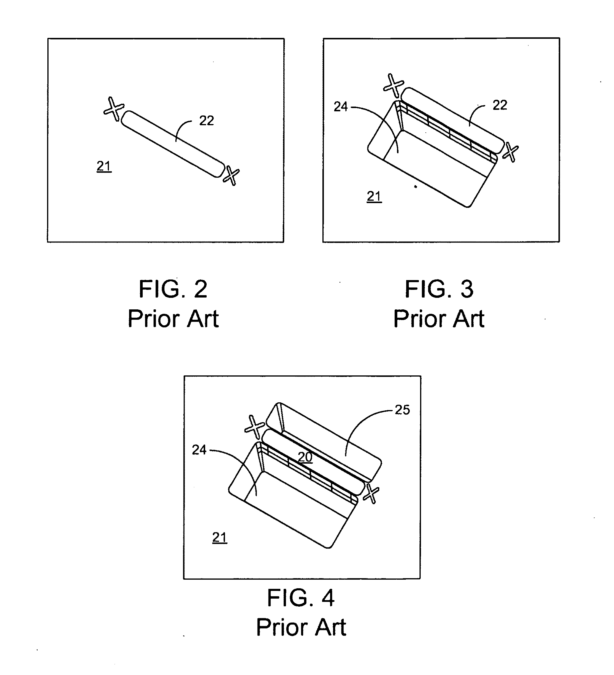
[0043]Current TEM lamella creation processes for FIB s...


PUM

PropertyMeasurementUnit
thickaaaaaaaaaa
thickaaaaaaaaaa
thickaaaaaaaaaa

Abstract

An improved method and apparatus for S / TEM sample preparation and analysis. Preferred embodiments of the present invention provide improved methods for TEM sample creation, especially for small geometry (<100 nm thick) TEM lamellae. A novel sample structure and a novel use of a milling pattern allow the creation of S / TEM samples as thin as 50 nm without significant bowing or warping. Preferred embodiments of the present invention provide methods to partially or fully automate TEM sample creation, to make the process of creating and analyzing TEM samples less labor intensive, and to increase throughput and reproducibility of TEM analysis.

Description

[0001]The present application claims priority from PCT Application No. PCT / US2007 / 082163, filed Oct. 22, 2007, and from U.S. Prov. Pat. App. No. 60 / 853,183, filed Oct. 20, 2006, which are hereby incorporated by reference.TECHNICAL FIELD OF THE INVENTION[0002]The present invention relates to preparation of samples and methods of analysis for transmission electron microscopes and scanning transmission electron microscopes.BACKGROUND OF THE INVENTION[0003]Semiconductor manufacturing, such as the fabrication of integrated circuits, typically entails the use of photolithography. A semiconductor substrate on which circuits are being formed, usually a silicon wafer, is coated with a material, such as a photoresist, that changes solubility when exposed to radiation. A lithography tool, such as a mask or reticle, positioned between the radiation source and the semiconductor substrate casts a shadow to control which areas of the substrate are exposed to the radiation. After the exposure, the ...

Claims


Application Information

Patent Timeline
09 Dec 2010
Publication
US20100308219A1
IPC
G01N23/00; G01N1/32
CPC
G01N1/32; H01J37/3056; H01J2237/208; H01J2237/31745; G01N23/04; H01J37/26; G01N1/06; G01N1/08
Inventors
BLACKWOOD, JEFF; STONE, STACEY