Type of High-Performance DC Amplification Device for Bioelectrical Signal Collection

a bioelectrical signal and dc amplification technology, applied in the field of electrochemical detection technology, can solve the problems of more parts applied, high interference voltage, and difficult to obtain neat bioelectrical signals accurately and quickly, and achieve the effects of simple design of bioelectrical front-end circuits, moderate production costs, and high performan

Inactive Publication Date: 2010-12-09
EDAN INSTR
View PDF3 Cites 27 Cited by
  • Summary
  • Abstract
  • Description
  • Claims
  • Application Information

AI Technical Summary

Benefits of technology

[0019]With the technical solution hereinabove, this invention has the following advantages:
[0020]1. High performance, noise and common-mod rejection ratio and other key indicators can reach a very level (anti-polarized voltage at ±600 mV, common-mode rejection ratio at 121 dB, noise at 12.5 uVpp) and the baseline is very stable;
[0025]This invention boasts the easy circuit structure, very high capability of bioelectrical signal acquisition, high circuit integration favorable to the miniaturization of boards and cards and remarkable economic and social benefit, which can be applied extensively to various bioelectrical detectors and detection systems for ECG, EEG and EMG (electromyography).

Problems solved by technology

Furthermore, the 50 / 60 HZ power interference from space coupling to human body may as high as dozens of volt and patient is a very complex signal source—its equivalent output impedance and polarized voltage are often in the changing status.
It is hard to obtain the neat bioelectrical signal accurately and quickly.
When a patient is in the unstable case (e.g., muscle contraction, electrode shift, etc.), the lead will produce higher interference voltage due to the presence of time constant circuit—such interference voltage will cause saturation to the first-stage amplifier output and then charge the capacitor.
Additionally, more parts are applied and the weak signal trace of printed circuit card is universally very long, allowing such devices are liable to the effects of the radiation sources of spatial interference and have the undesirable anti-interference capability.3. With high gain of amplifier and small dynamic range of signal for such devices, a subtle signal disturbance (e.g., muscle contraction, electrode shift) will easily cause the saturation of amplifier in the clinical application.
It will take a very long for the baseline to recover due to the effects of the time constant circuit and this means a fatal defect in the field of the clinical ECG detection—it is difficult for a doctor to bear the amplifier saturation and baseline drift problems arising from the baseline drift.4. PACE pulse detection problem.
Such problem is also cause by the attribute of AC structure.
Thus it is hard for the AC amplification structure to detect PACE signal effectively.5. Losing the DC component of signal source and the AC signal close to the DC signal.
With the exceptions and other effects with regard to ST section in the field of ECG detection, it is hard to provide the non-distorted accurate waveforms to doctors.6. High source voltage is not conducive to low power consumption.
Such AD amplification devices often apply the higher source voltage to ensure the dynamic range and gain and such practice is unfavorable to the control of power consumption of boards and cards and disagrees with the industrial development trend of low voltage and low power consumption.

Method used


Image

  • Type of High-Performance DC Amplification Device for Bioelectrical Signal Collection
  • Type of High-Performance DC Amplification Device for Bioelectrical Signal Collection
  • Type of High-Performance DC Amplification Device for Bioelectrical Signal Collection

Examples


Embodiment Construction

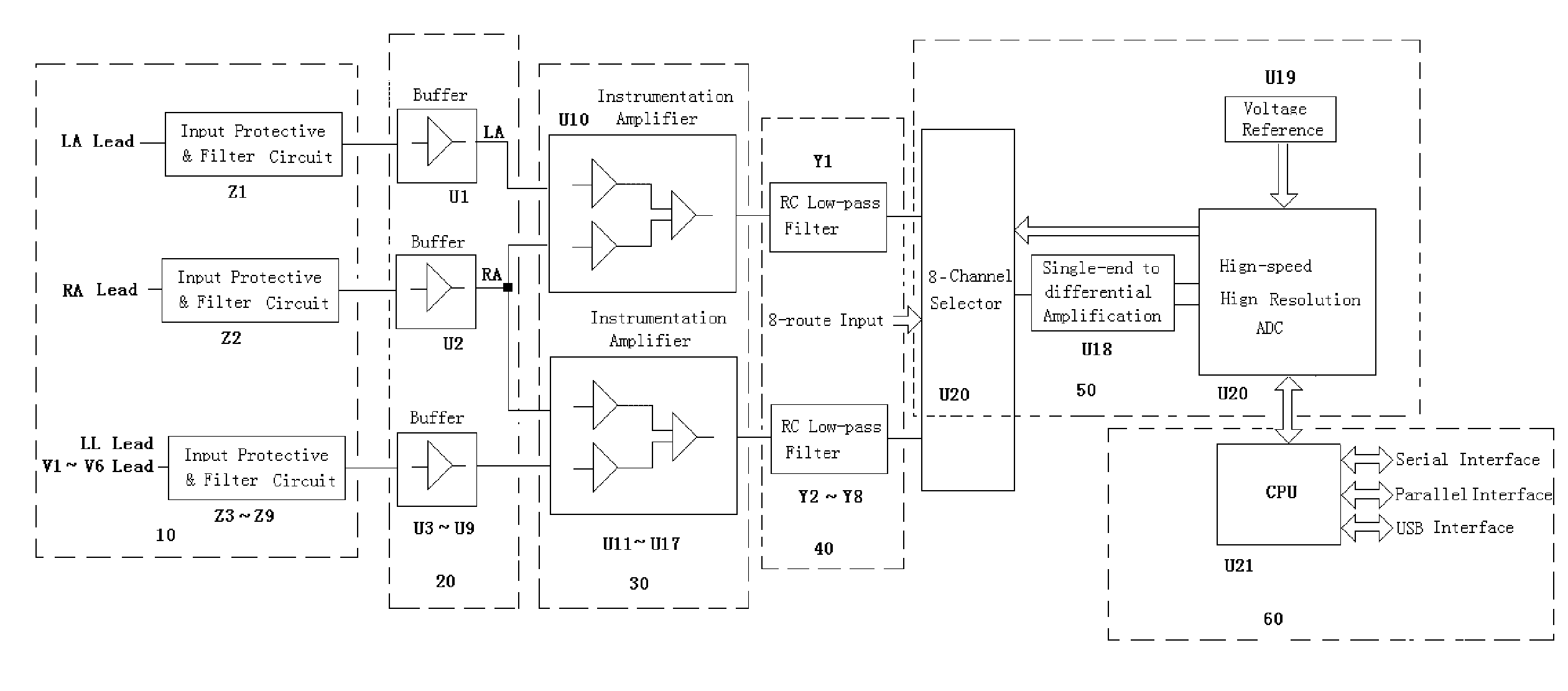
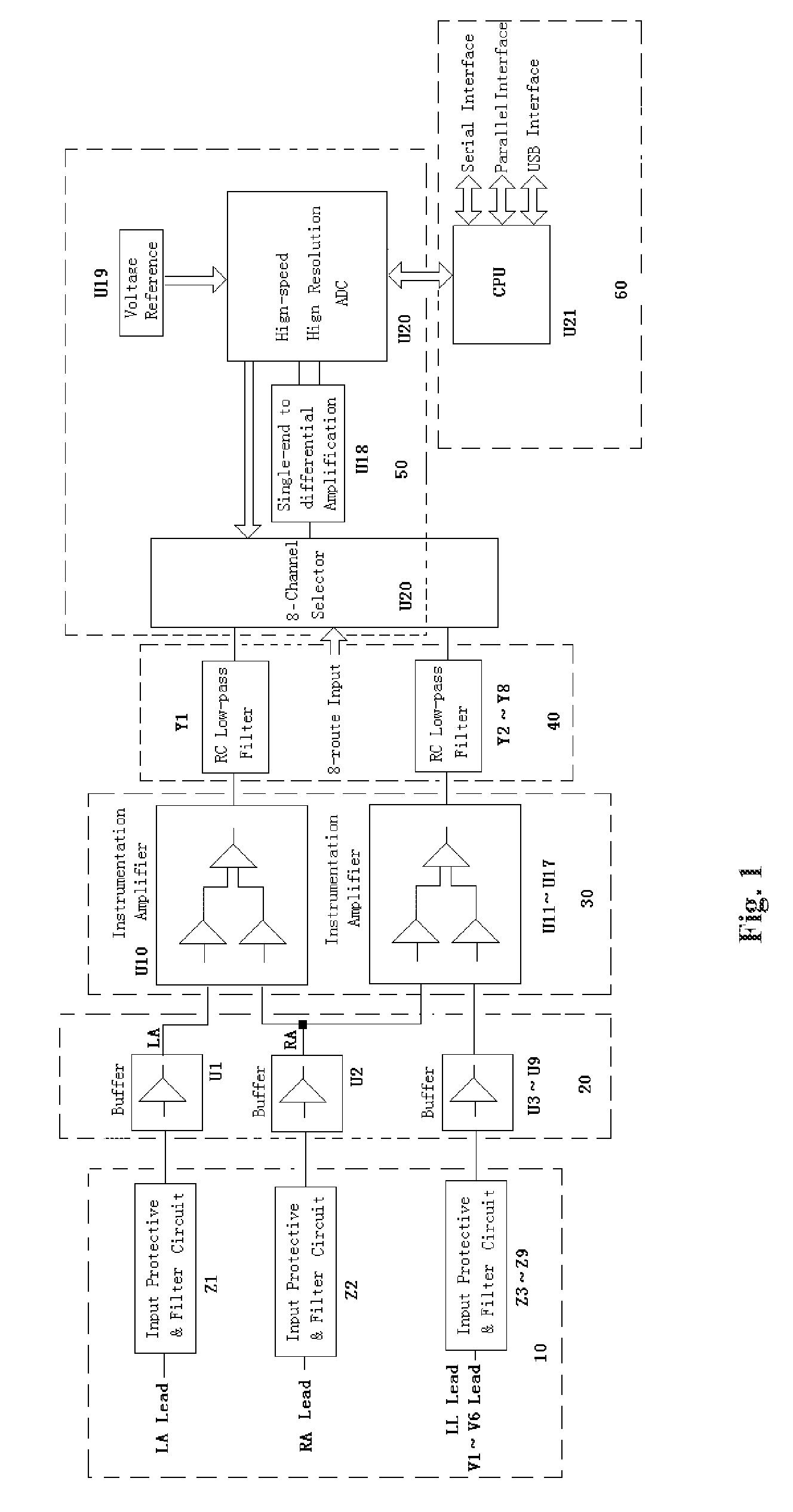
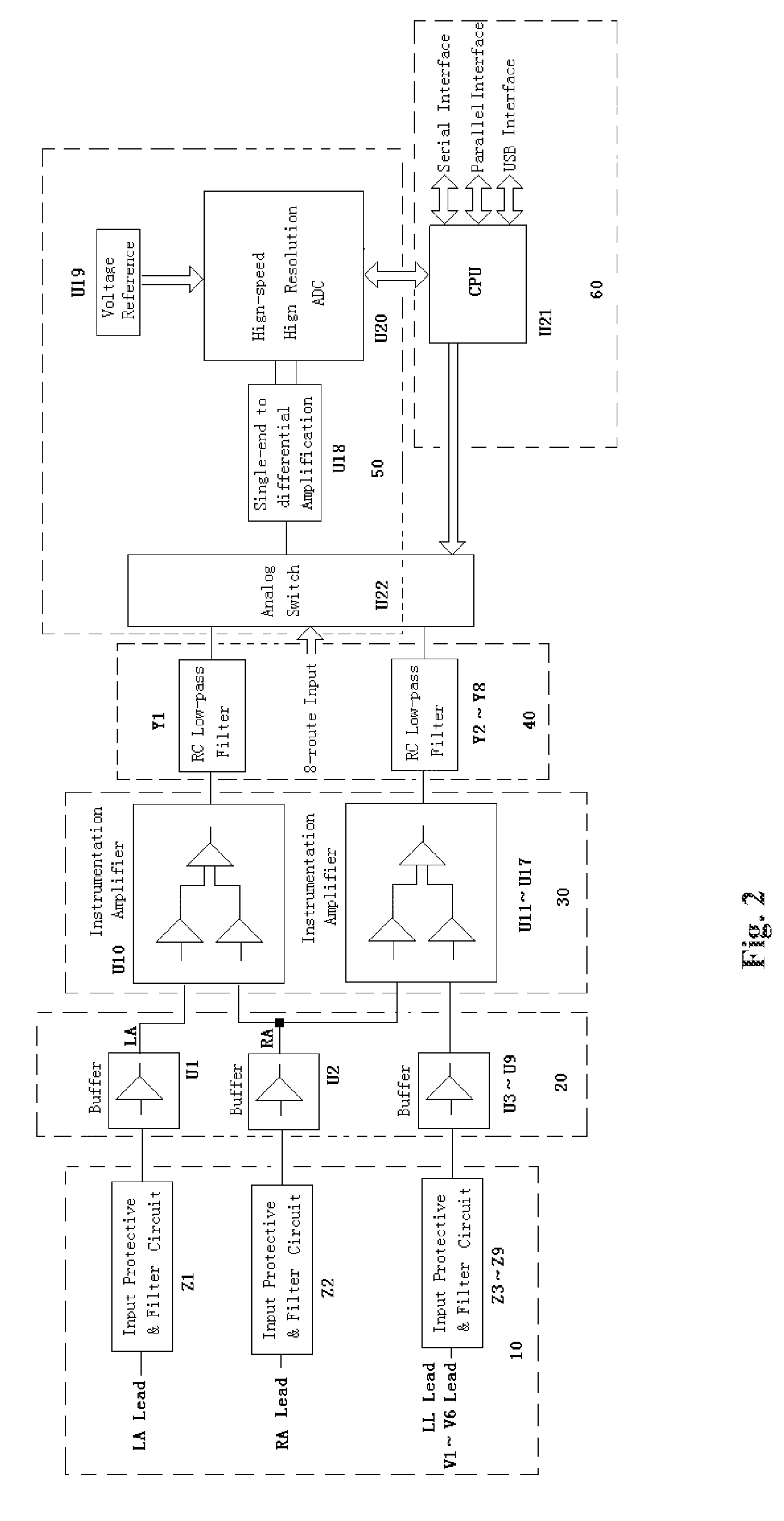
[0028]This invention is further described on the basis of the attached figures as below: Shown as FIG. 1 and FIG. 2, the present invention involves in a type of high-performance DC amplification device for bioelectrical signal collection, which includes the input protective / filter circuit (10), input buffer circuit (20), instrumentation amplification circuit (30), RC low-pass filter circuit (40) and analog-digital conversion and peripheral circuit (50) and CPU (60), whereas the input protective / filter circuit (10) collects the bioelectrical signal and sends such signal to the input buffer circuit (20) and then allows it pass through the instrumentation amplification circuit (30), RC low-pass filter circuit (40) and analog-digital conversion and peripheral circuit (50) in order. The CPU (60) controls the operation of analog-digital conversion and peripheral circuit (50).

[0029]The input protective / filter circuit (10) has nine routes from Z1 to Z9 and each route is composed of a gas di...


PUM


Abstract

This invention relates to a high-performance DC amplifying device for bioelectrical signal collection, including the sequentially linked input protective / filter circuit, input buffer circuit, instrumentation amplification circuit, RC low-pass filter circuit, analog-digital conversion and peripheral circuit and CPU, as described as below: the input protective / filter circuit collects the bioelectrical signal and sends such signal to the input buffer circuit and then allows it pass through the instrumentation amplification circuit, RC low-pass filter circuit and analog-digital conversion and peripheral circuit in order. For such device, CPU controls the operation of analog-digital conversion and peripheral circuit. This invention converts the impedance of bioelectrical signal firstly and then applies the common-mode signal rejection to the amplified signal, with the high-frequency noise filtered; such signal is treated for the secondary amplification by the single-ended-to-differential operational amplifier—the noise and common-mode rejection ratio and other indicators of such signal after analog-digital conversion reach a very high level and the baseline is very stable; the dynamic range of signal input is large and it is not saturated easily. With fewer parts needed, the reliability of such device is enhanced.

Description

TECHNICAL FIELD[0001]This invention involves in the field of an electronic detection technology, specifically in the detection of the weak bioelectrical signal and particularly in the high-performance DC amplification device for bioelectrical signal collection.BACKGROUND ART[0002]The current weak bioelectrical signal detection is conducted with the strong background interference and the patient's polarized voltage, in which the bioelectrical signal on the surface of human body is at the MV level only and the polarized voltage is often at hundreds of MV. Furthermore, the 50 / 60 HZ power interference from space coupling to human body may as high as dozens of volt and patient is a very complex signal source—its equivalent output impedance and polarized voltage are often in the changing status. It is hard to obtain the neat bioelectrical signal accurately and quickly. The more complicated AC amplification circuit structure is universally applied so far, including buffer, instrumentation ...

Claims


Application Information

Patent Timeline
Patent Type & Authority Applications(United States)
IPC IPC(8): H03F1/00
CPCH03F3/387H03F2200/321H03F2200/261
Inventor XIANG, XIAOFEIHU, XUNQIAOKONG, LINGFENGQIU, SIHAI
Owner EDAN INSTR
Why Eureka
Try Eureka