
Aligned collagen and method therefor

a technology of aligned collagen and constructs, which is applied in the direction of prosthesis, peptide/protein ingredients, microfluidic channels, etc., can solve the problems of inability to make macroscale collagenous constructs, and inability to achieve high packing density, etc., to achieve the effect of increasing the crosslinking density of the construct and low cos

Inactive Publication Date: 2010-12-09
PURDUE RES FOUND INC
View PDF10 Cites 13 Cited by
  • Summary
  • Abstract
  • Description
  • Claims
  • Application Information

AI Technical Summary

Benefits of technology

[0008]There are several unique advantages of the electrochemical process described herein: (1) environmentally friendly (no toxic solvents used compared to electrospinning to produce collagen fibers); (2) low cost (low electric voltage and current); (3) practicality of the experimental set up (pair of electrodes in a humid environment), which can be upgradeable to batch processing by employing electrode arrays; (4) ability to produce long rope-like constructs which may be useful in regeneration of longer tendons such as the flexors or extensors of the finger.
[0009]The aligned collagen constructs formed by the electrochemical methods described herein are anisotropic and exhibit mechanical properties similar to those of native tendons. Furthermore, the mechanical properties of the resultant collagen fiber bundles, after cross-linking, exhibit an ultimate tensile strength and tensile modulus similar to native tendon. In one embodiment, the mechanical properties of the constructs described herein can be further modified by incorporation of non-collageneous proteins (e.g., fibronectin, fibrinogen, keratin, and silk proteins) and proteoglycans (e.g., decorin) and by increasing the crosslinking density of the constructs. In one embodiment, the constructs described herein may be used to replace load-bearing connective tissues.
[0028]FIG. 7. shows the pH-gradient between parallel electrodes and a schematic representation of collagen alignment and the congregation mechanism: Panel A) universal pH indicator dye revealed the pH-gradient in the collagen solution between the anode (acidic) and the cathode (basic); Panel B) auto-fluorescent confocal image showing that all of the collagen in the solution was congregated along a fixed band via isoelectric focusing. The aligned collagen band was highly birefringent. (inset, bar=200 μm); Panel C) schematic representation of the electrochemical assembly of collagen molecules. 1=Rotatory alignment, the pH-gradient and electrostatic interactions rotate the molecules normal to the electric field; 2=Isoelectric focusing, charged collagen molecules move towards the isoelectric point where they become uncharged and their mobility is arrested (in actual events, stage 1 and stage 2 are likely to happen simultaneously); 3=Assembly, the high concentration of collagen due to congregation at the isoelectric point and the basic pH between the cathode and isoelectric point facilitate fibrillar assembly of molecules into a macroscale bundle. Depending on the electrodes configuration, collagen can be formed into straight fibers or rings (tubes).
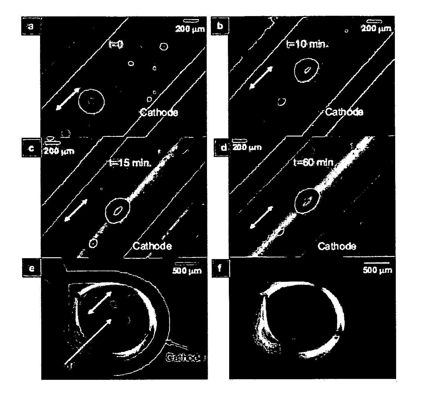
[0029]FIG. 8. Time-elapsed compensated polarized optical images of a collagen bundle and a ring formed under electrochemical effects. Panels A-D show that the collagen band structure grows with time at a location between the electrodes. Molecules which are oriented parallel and perpendicular to the slow axis of the gypsum plate (white double arrow) appear blue and yellow, respectively. Note that the entrapped air bubbles (intentionally introduced inside the collagen solution by mixing) changed from circular to elliptical due to lateral compressive forces. This compression force is a result of molecular congregation during isoelectric focusing and improves the orientation and packing density of collagen molecules. Panel E shows a compensated polarized optical image of a collagen ring with molecules aligned circumferentially as evidenced by blue and yellow gradations about the circumference in different orthogonal quadrants. Panel F shows a polarized image showing that the collagen ring is highly birefringent.

Problems solved by technology

Controlled assembly of collagen molecules in vitro remains a major challenge for engineering the next generation of tissues.
The alignment of collagen molecules by flow, mechanical extrusion, microfluidic channels, or anisotropic chemical nanopatterns has limitations in attaining high packing density, elastic deformability, and in making constructs of relevant sizes.
As a consequence, there is currently no practical means to form highly oriented, densely-packed macroscale collagenous constructs on the timescale of minutes to hours.

Method used


Image

  • Aligned collagen and method therefor
  • Aligned collagen and method therefor
  • Aligned collagen and method therefor

Examples


example 1

Electrochemical Alignment of Collagen

[0093]Ten mL of type-I collagen (6 mg / mL 97% bovine hide, INAMED Corporation, Santa Barbara, Calif.) was dialyzed (MWcut off=3.5 kDa) against ultrapure water at 5° C. for 72 hours to remove salts. The dialyzed collagen had the characteristics of normal acidic soluble monomeric collagen and did not undergo fibrillogenesis before the onset of the electrochemical process which took place at room temperature (FIG. 21). The dialyzed collagen underwent fibril formation only after the addition of 10× phosphate buffered saline (PBS) and adjustment of the temperature to 37° C. at pH 7.4 (FIG. 21). This indicates that the dialyzed collagen mainly existed in molecular form instead of fibrillar form at the onset of electric current application.

[0094]Two stainless steel electrode wires (0.003″ diameter, Sigmund Cohen Corporation, New York) were stripped of their insulating sheet along an inch-long segment and positioned parallel on a glass slide with separati...

example 2

Electrochemically-Induced Controlled Collagen Self-Assembly Process

[0103]The controlled collagen self-assembly process depicted in FIG. 7, Panel C, is composed of rotary alignment, isoelectric focusing and pH induced self-assembly. The mechanism of this process is also evident by time-elapsed polarized optical images acquired during electrochemically induced fibrillogenesis (FIG. 8, Panels A-D). The migration of collagen molecules towards the isoelectric point compressively deformed the shape of intentionally induced air bubbles from circular to elliptical. Also, the width of the collagen band increased with time and became more birefringent as all molecules aligned and assembled at the isoelectric point. The crystalline quality and orientation of the resulting collagen band was confirmed by its uniform and strong blue interference color when the collagen construct was viewed under crossed-polarizers coupled with a gypsum plate positioned at 45° (FIG. 8, Panels C-D). This indicates ...

example 3

Varying Geometry of Collagen Construct

[0104]To demonstrate the versatility of this electrochemical alignment technique for the generation of macroscale constructs of various shapes, a wire was bent into a circular cathode and a point-source anode was placed at the center of the ring (FIG. 14, Panel C). This configuration yielded a ring-shaped collagenous construct close to the cathode region. Using the gypsum plate and crossed-polarizers, it was confirmed that the molecules were circumferentially oriented within the ring, as evident by the blue and the yellow appearance in directions parallel and perpendicular to the slow axis of the gypsum plate, respectively (FIG. 8, Panel E). Without the gypsum plate, the collagen ring was highly birefringent under crossed-polarizers (FIG. 8, Panel F).


PUM

PropertyMeasurementUnit
densityaaaaaaaaaa
current densityaaaaaaaaaa
electric field strengthaaaaaaaaaa

Abstract

Compositions and methods of preparing a graft construct comprising aligned collagen fibrils, wherein the construct is anisotropic, are described. The construct is prepared by application of an electrochemical field and a pH gradient to solutions containing collagen. In accordance with this method, collagen aligns at its isoelectric point to form anisotropic constructs.

Description

CROSS REFERENCE TO RELATED APPLICATIONS[0001]This application claims the benefit under 35 U.S.C. §119(e) of U.S. Provisional Application Ser. No. 60 / 991,536, filed on Nov. 30, 2007, incorporated herein by reference in its entirety. This application also claims the benefit under 35 U.S.C. §119(e) of U.S. Provisional Application Ser. No. 61 / 048,840, filed on Apr. 29, 2008, incorporated herein by reference in its entirety.GOVERNMENT RIGHTS[0002]Research relating to this invention was supported in part by the U.S. Government under Grant No. NSF CAREER-0449188 awarded from the National Science Foundation. The U.S. Government has certain rights in this invention.FIELD OF THE INVENTION[0003]The invention relates to compositions and methods of preparing an engineered graft construct comprising aligned collagen fibrils, wherein the construct is anisotropic.BACKGROUND AND SUMMARY OF THE INVENTION[0004]Collagen is the major structural protein in connective tissues such as skin, bone, ligaments...

Claims


Application Information

Patent Timeline
Patent Type & Authority Applications(United States)
IPC IPC(8): C07K14/78
CPCA61L27/24C25B7/00A61L2430/32A61L27/38
Inventor AKKUS, OZANPANITCH, ALYSSACHENG, XINGGUO
Owner PURDUE RES FOUND INC
Learn More