Spin torque transfer MRAM design with low switching current

Inactive Publication Date: 2010-12-16
HEADWAY TECH INC
View PDF32 Cites 7 Cited by
  • Summary
  • Abstract
  • Description
  • Claims
  • Application Information

AI Technical Summary

Benefits of technology

[0032]These objects have been achieved by providing a STT based MRAM design whose critical switching current has been reduced to be less than that of any of the known earlier designs. This has been achieved through the addition of a spin filtering layer (SFL) to the device as well as by including a nano-current channel (NCC) whose function is to confine the current flowing through the device locally, thereby maximizing the current density through its part of the free layer.
[0033]Thus, above the critical current, STT induced magnetization switching takes effect inside the NCC first but the resulting magnetization is s

Problems solved by technology

However, if the second spacer is metal, the damping constant, α, can experience a significant, and detrimental, increase due to spin pumping (see Ref.
Also, the free layer, the second spacer and the second pinned layer effectively form another MTJ or SV whose dr/r is in the opposite direction, thereby undesirably reducing the net read signal.
This reduction of dr/r is most detrimental if the second spacer is a tunneling insulator.
However, giving the second tunneling insulator such a low resistance.area product is very difficult as well as being prone to dielectric breakdown.
Such a structure is, however, very difficult t

Method used


Image

  • Spin torque transfer MRAM design with low switching current
  • Spin torque transfer MRAM design with low switching current
  • Spin torque transfer MRAM design with low switching current

Examples


Embodiment Construction

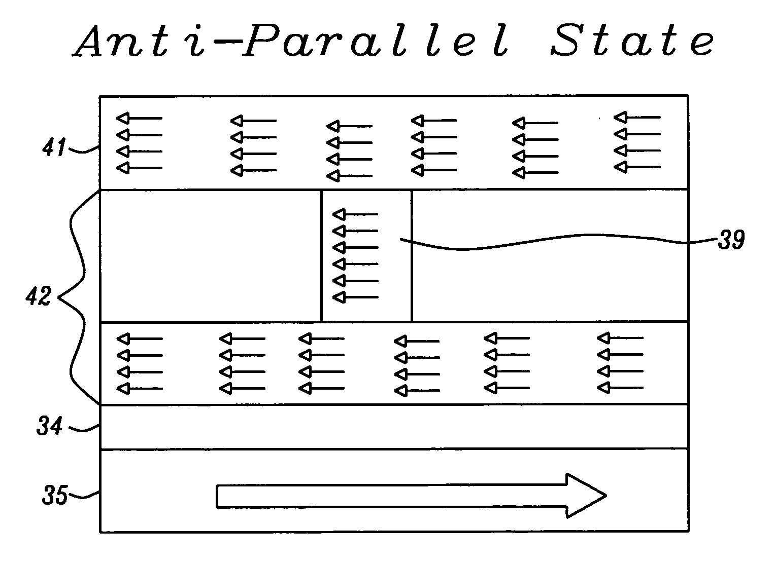
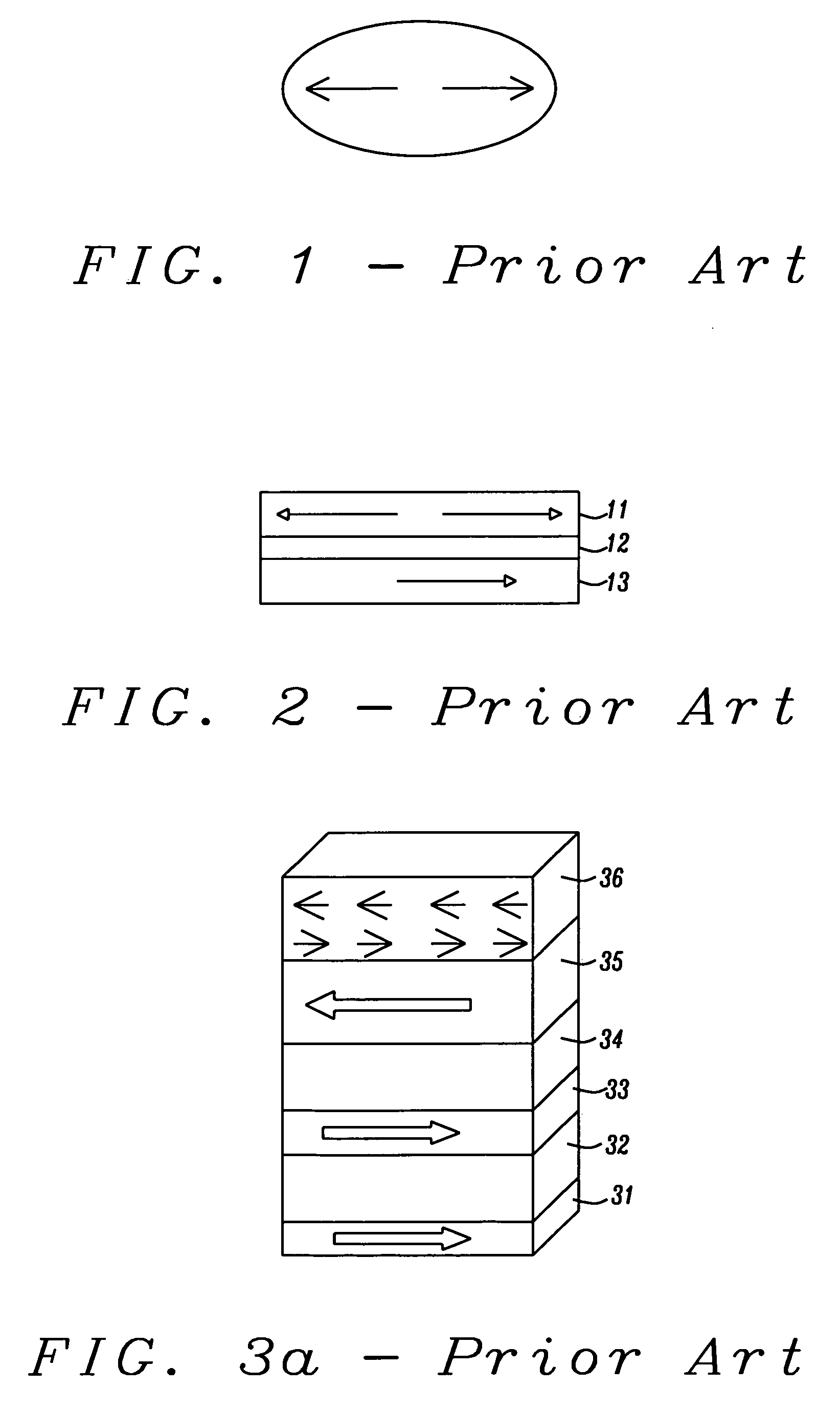
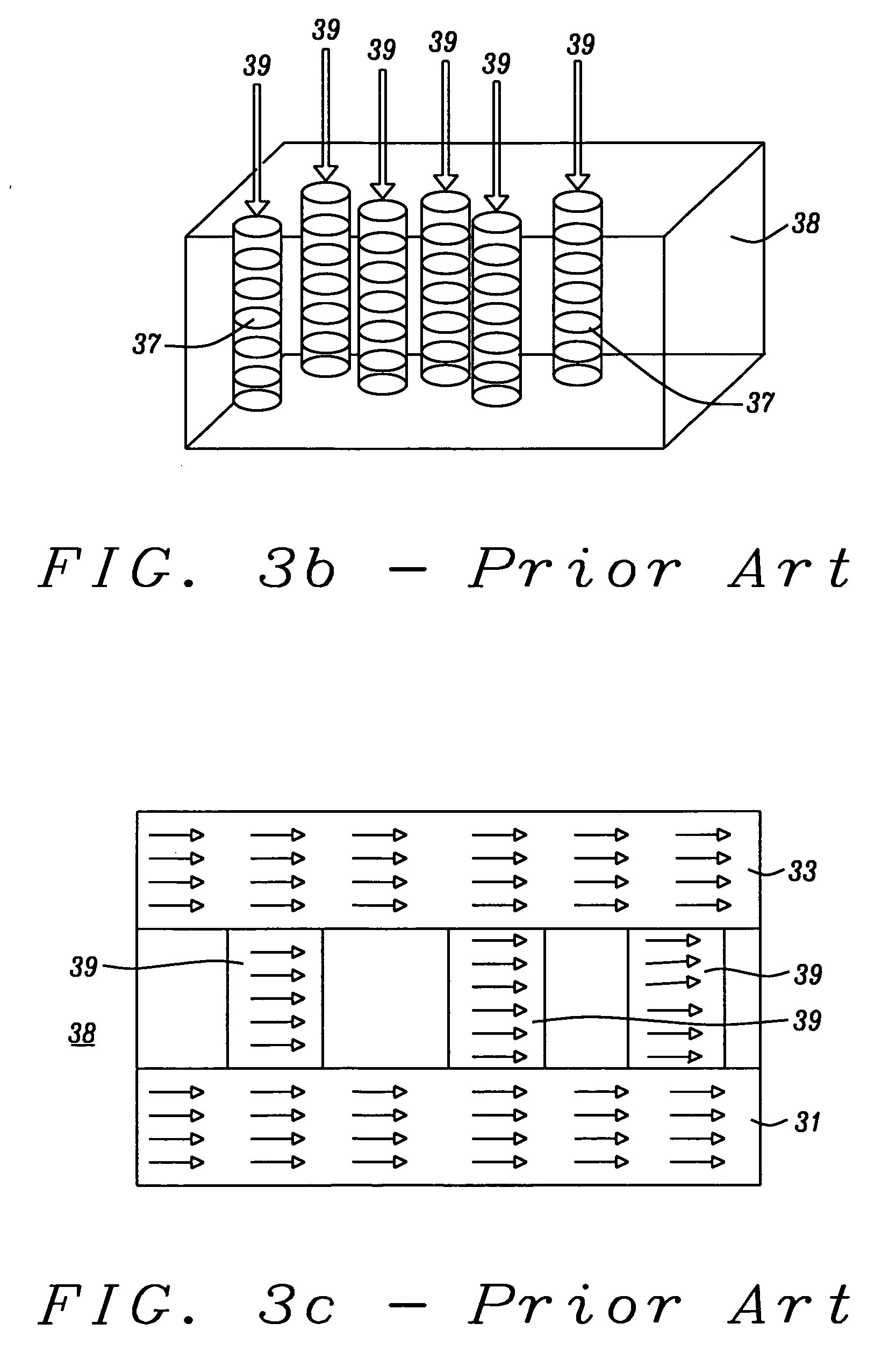
[0042]The invention discloses a STT based MRAM design whose critical switching current has been reduced to be less than that of any of the earlier designs described above. This has been achieved through use of the structure shown in FIG. 4. In part this structure is similar to FIG. 3c (order of layers inverted) and includes NCC layer 32, ferromagnetic layer (FML) 33, insulating spacer layer 34, and pinned layer 35. Anti-ferromagnetic layer 36 is also part of the invented structure but is not shown in FIG. 4.

[0043]If the FML is too strongly coupled with the NCC, switching of the latter through STT could be compromised so it is an important feature of the invention that it is critical for the coupling strength between NCC 32 and FML 33 to be less than about 40 Oe. Conversely, if the coupling is too weak (less than about 3.6 Oe), switching the NCC may have no effect on the FML.

[0044]Achieving an optimum coupling strength between NCC 32 and FML 33 was accomplished by adjusting the compo...


PUM


Abstract

The invention discloses a method to store digital information through use of spin torque transfer in a device that has a very low critical current. This is achieved by adding a spin filtering layer whose direction of magnetization is fixed to be parallel to the device's pinned layer.

Description

FIELD OF THE INVENTION[0001]The invention relates to the general field of Magnetic Random Access memory (MRAM) more particularly to devices in which switching is achieved through spin torque transfer that occurs when current through a given memory cell exceeds some critical value.BACKGROUND OF THE INVENTION[0002]Magnetic tunneling junctions (MTJ) and giant magneto-resistance (GMR) Spin Valves (SV) comprise two ferromagnetic layers separated by a non-magnetic layer. In MTJs this is a tunneling oxide layer while in GMR-SVs it is a good metallic conductor layer. They have been widely studied for use as memory elements in magnetic random access memories (MRAM). Usually the magnetization of one of the ferromagnetic layers is in a fixed direction (i.e. it is a pinned layer), while the other layer is free to switch its magnetization direction, and is usually called the free layer.[0003]For MRAM applications, the storage of the digital information is encoded as the direction of magnetizatio...

Claims


Application Information

Patent Timeline
IPC IPC(8): G11C11/14H01L21/00H01L29/82
CPCB82Y10/00B82Y25/00B82Y40/00G11C11/16H01F10/3268H01F41/303G11C11/161H01L29/66984H01L43/08H01L43/12H01F10/329H01F10/3259H01F41/325H01F41/307H10N50/10H10N50/01
Inventor MIN, TAIKULA, WITOLD
Owner HEADWAY TECH INC
Why Eureka
Try Eureka