Phase-contrast imaging method and apparatus

a phase-contrast imaging and phase-contrast technology, applied in the direction of photometry using electric radiation detectors, optical radiation measurement, instruments, etc., can solve the problems of severe practical difficulties, difficult interpretation of interferograms, and possible phase estimation ambiguities

Inactive Publication Date: 2010-12-30
COMMONWEALTH SCI & IND RES ORG
View PDF10 Cites 21 Cited by
  • Summary
  • Abstract
  • Description
  • Claims
  • Application Information

AI Technical Summary

Benefits of technology

68]The method may include selecting the images to have working points that allow acc

Problems solved by technology

However, it typically requires highly monochromatic radiation (of Δλ/λ˜10−4), precise alignment of the crystals (being highly susceptible to mechanical and thermal instabilities).
Also, interferograms are difficult to interpret and typically require more than one interferogram to be recorded for a given sample because of the modulo 2π ambiguity.
Image processing is required for visualisation of phase, and severe practical difficulties arise when imaging even moderately thick objects.
However, analyser-based imaging typically uses quasi-monochromatic radiation (of Δλ/λ˜10−4), and is usually sensitive to only one component of the phase gradient leading to possible ambiguities in phase estimation.
It also requires an effectively perfect analyser crystal that itself must be very precisely controlled in orientation; although bent-crystal optics can help to overcome some limitations, their use can lead to other complications.
However, grating-based imaging is sensitive to only one component of the phase gradient, requires precise alignment of the gratings at a significant separation distance (in two gratin

Method used


Image

  • Phase-contrast imaging method and apparatus
  • Phase-contrast imaging method and apparatus
  • Phase-contrast imaging method and apparatus

Examples


examples

[0189]Firstly, numerical experiments (viz. simulations of apparatus 10) and comparative examples were conducted using rigorous wave-optical theory based on Fresnel diffraction formula, in various imaging configurations.

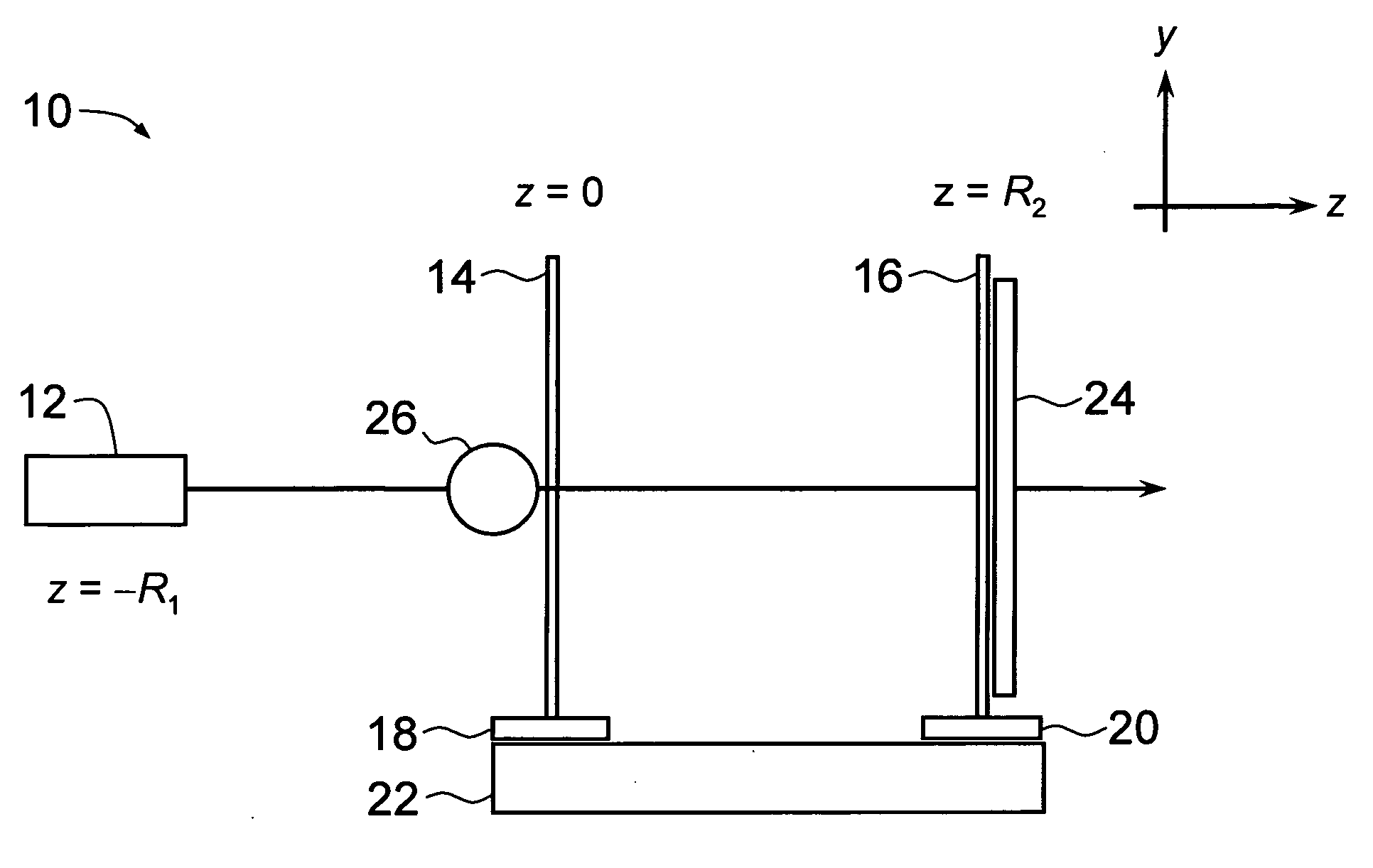
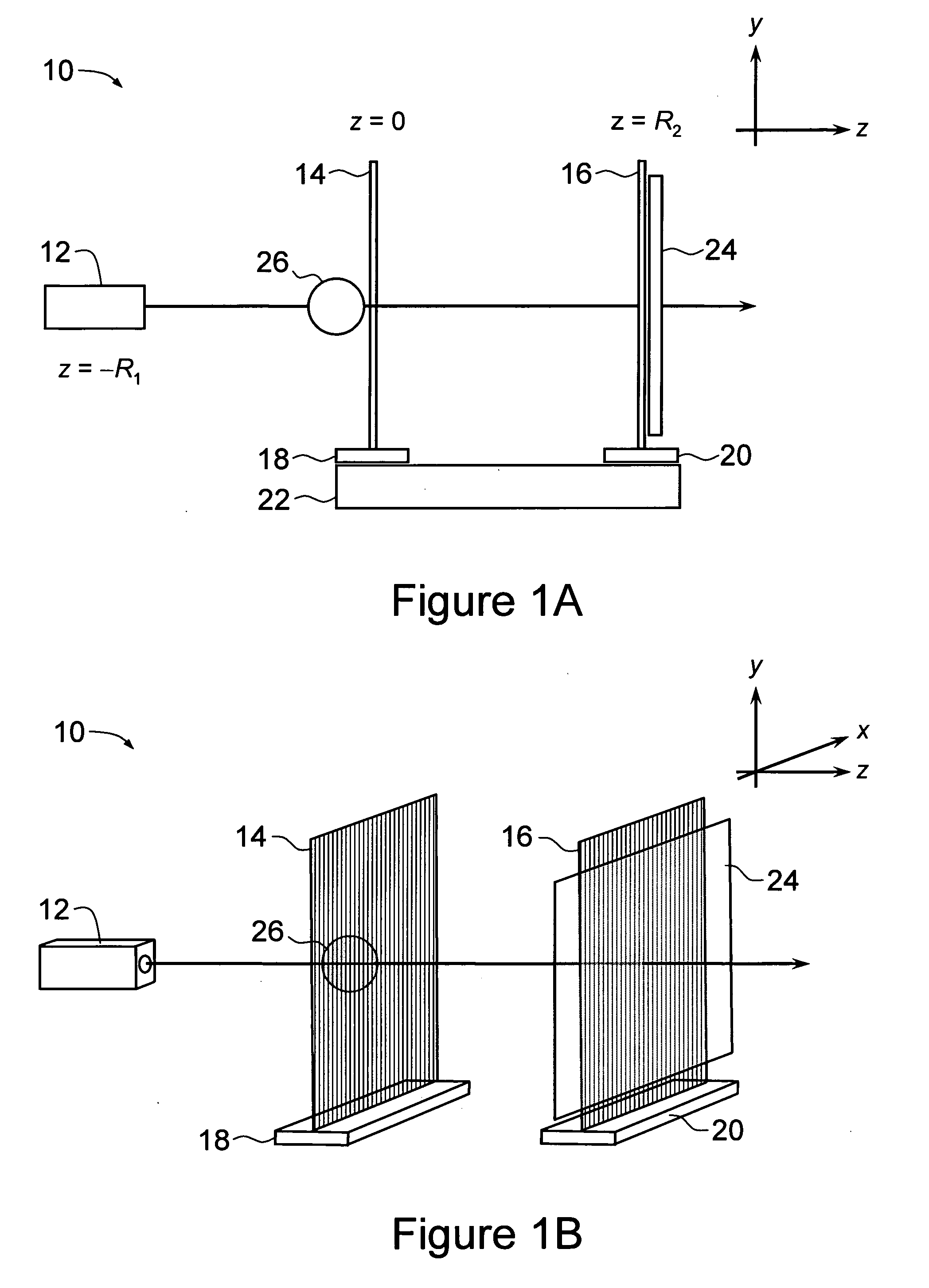
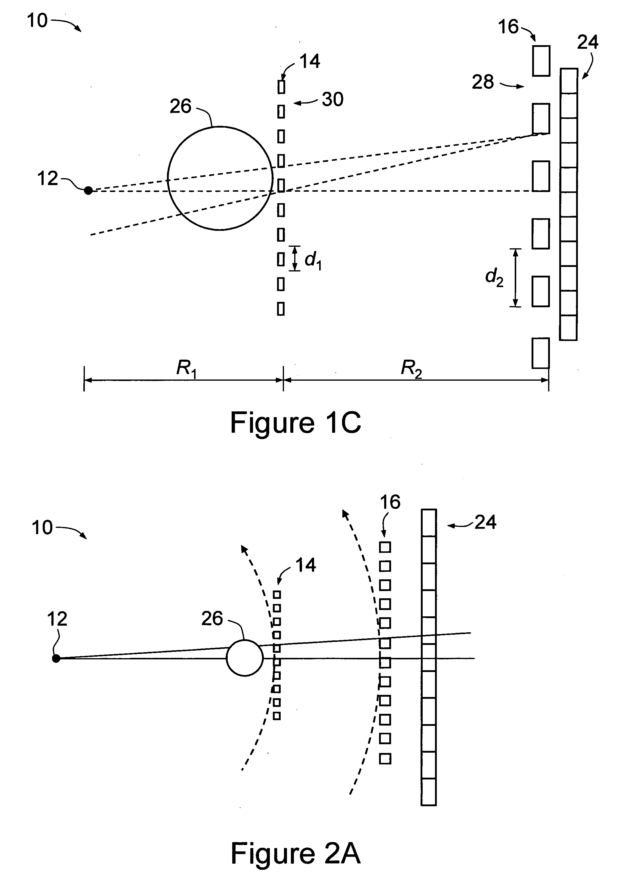
[0190]In the first set of simulations, gratings 14, 16 were simulated as stationary during image collection, as having the same period of rectangular modulation, d=8 μm, and as having the same line-to-space ratio, 1:1; an X-ray wavelength of λ=0.62 Å, corresponding to an energy of 20 keV, was employed. The maximum phase shift of the phase grating (i.e. first grating 14) was n / 2. The distance between first and second gratings 14, 16 was R2=d2 / (2λ)=0.516 m. This is the distance at which a self-image of the phase grating 14 is produced [17]. An object 26 comprising a pure phase-object sphere of diameter 250 μm, radially smeared with a Gaussian function of 12.5 μm FWHM, and maximum phase shift of −2 rad, was simulated. A plane incident wave was assumed in this and subsequ...


PUM


Abstract

A phase-contrast imaging apparatus for imaging an object, comprising a radiation source, a first diffracting optical element located to receive radiation from the source, a second diffracting optical element located after the first optical element, a spatially resolving detector for detecting radiation from the source that has propagated through the object and been diffracted sequentially by the first optical element and the second optical element and an actuator for providing a relative translation of the first and second optical elements with respect to and across a propagation direction of radiation transmitted from the source to the detector. The actuator provides the relative translations of the first and second optical element at respectively a first speed and a second speed that is the first speed times a magnification factor of the apparatus.

Description

RELATED APPLICATION[0001]This application is based on and claims the benefit of the filing date of AU application no. 2007906826 filed 14 Dec. 2007, the content of which as filed is incorporated herein by reference in its entirety.FIELD OF THE INVENTION[0002]The present invention relates to a phase-contrast imaging method and apparatus, of particular but by no means exclusive application in phase-contrast imaging using x-rays or neutrons.BACKGROUND OF THE INVENTION[0003]The most long-standing method for X-ray imaging (i.e. radiography) is based on absorption and dates back to the pioneering work of Röntgen (who discovered X-rays in 1895). More recently, other mechanisms for X-ray imaging have been developed including those involving phase contrast. These methods are sensitive to the real part of the complex refractive index for the interaction between electromagnetic radiation and matter. They also depend on the use of wave optics for their proper description (cf. conventional radio...

Claims


Application Information

Patent Timeline
IPC IPC(8): G01J1/42
CPCG01N23/041G02B26/0808G02B27/52
Inventor NESTERETS, YAKOVWILKINS, STEPHEN WILLIAM
Owner COMMONWEALTH SCI & IND RES ORG
Why Eureka
Try Eureka