Optical element and method for producing the same

Inactive Publication Date: 2010-12-30
ASAHI GLASS CO LTD
View PDF17 Cites 18 Cited by
  • Summary
  • Abstract
  • Description
  • Claims
  • Application Information

AI Technical Summary

Benefits of technology

[0028]According to the optical element of the invention, the optically functional film formed on the surface of the glass optical element using the phosphate glass or the fluorophosphate glass as a glass material is not corroded even in an atmosphere of high temperature and high humidity, and the occurrence of cloudiness can be effec

Problems solved by technology

However, in the method (1), no matter how densely the film is formed as the first layer, the glass is barely exposed at the side surface of the coated lens.
Accordingly, it has been found that when the coated lens is placed in an atmosphere of high humidity, a phosphate component is eluted out from the side surface and reacts with an optical surface of the coated lens, resulting in the occurrence of cloudiness in the lens.
Accordingly, when the glass material having poor environmental durability is immersed therein, the glass surface becomes clouded, or the glass itself is dissolved away, in some cases.
There has therefore been a limitation on the glass material to be applicable.
Furthermore, when the whole surface coating as described

Method used


Image

  • Optical element and method for producing the same
  • Optical element and method for producing the same
  • Optical element and method for producing the same

Examples


example 1

Conventional Example 1

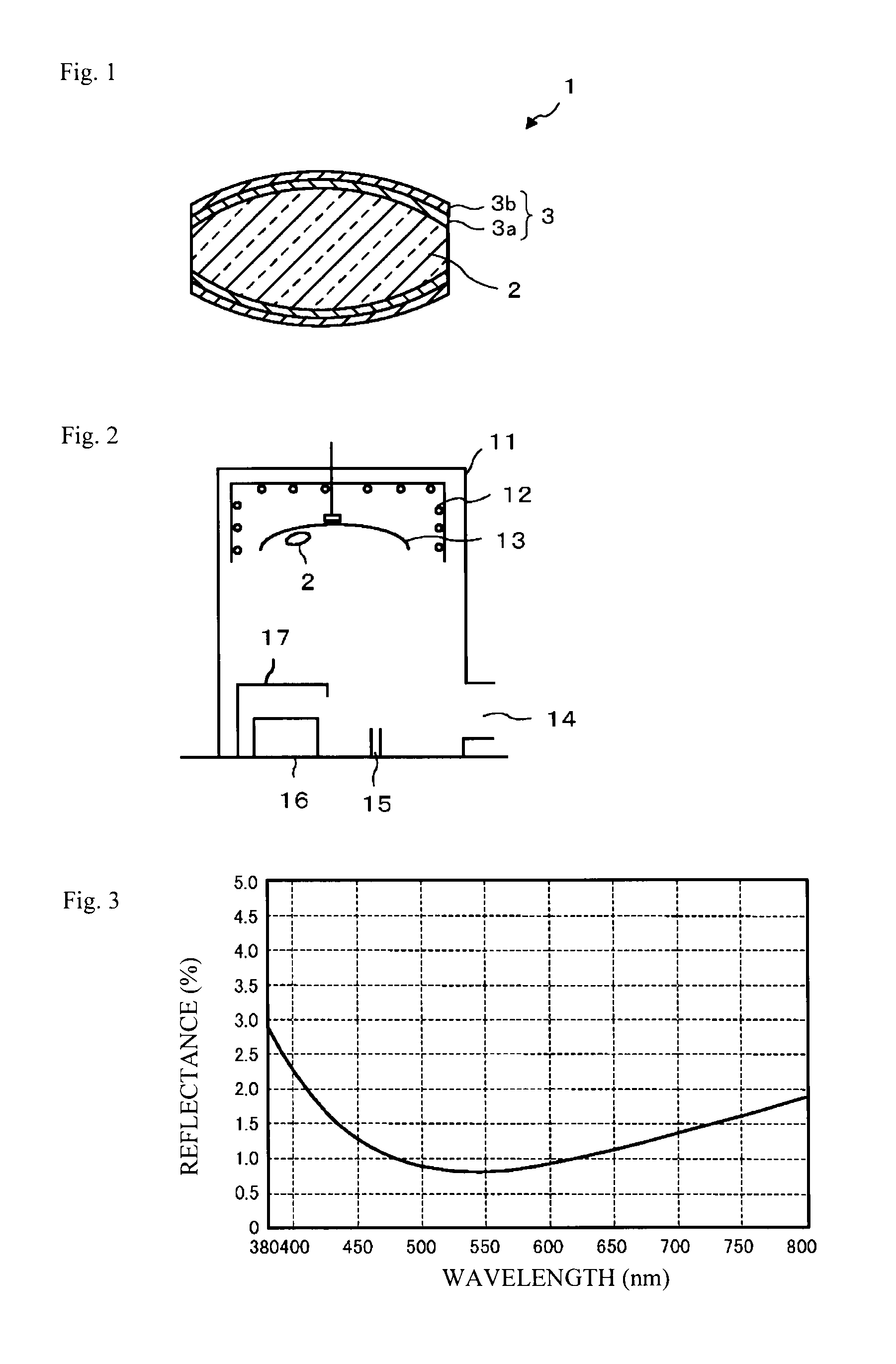
[0115]The constitution of an antireflection film in which a monolayer film of magnesium fluoride (MgF2) was formed on the surface of the core glass is shown in Table 4, and the reflection characteristic thereof is shown in FIG. 3. This characteristic is hereinafter called the single characteristic.

TABLE 4Vapor-Deposited MaterialActual Thickness (nm)First LayerMgF297.62AIR

examples 1 to 3

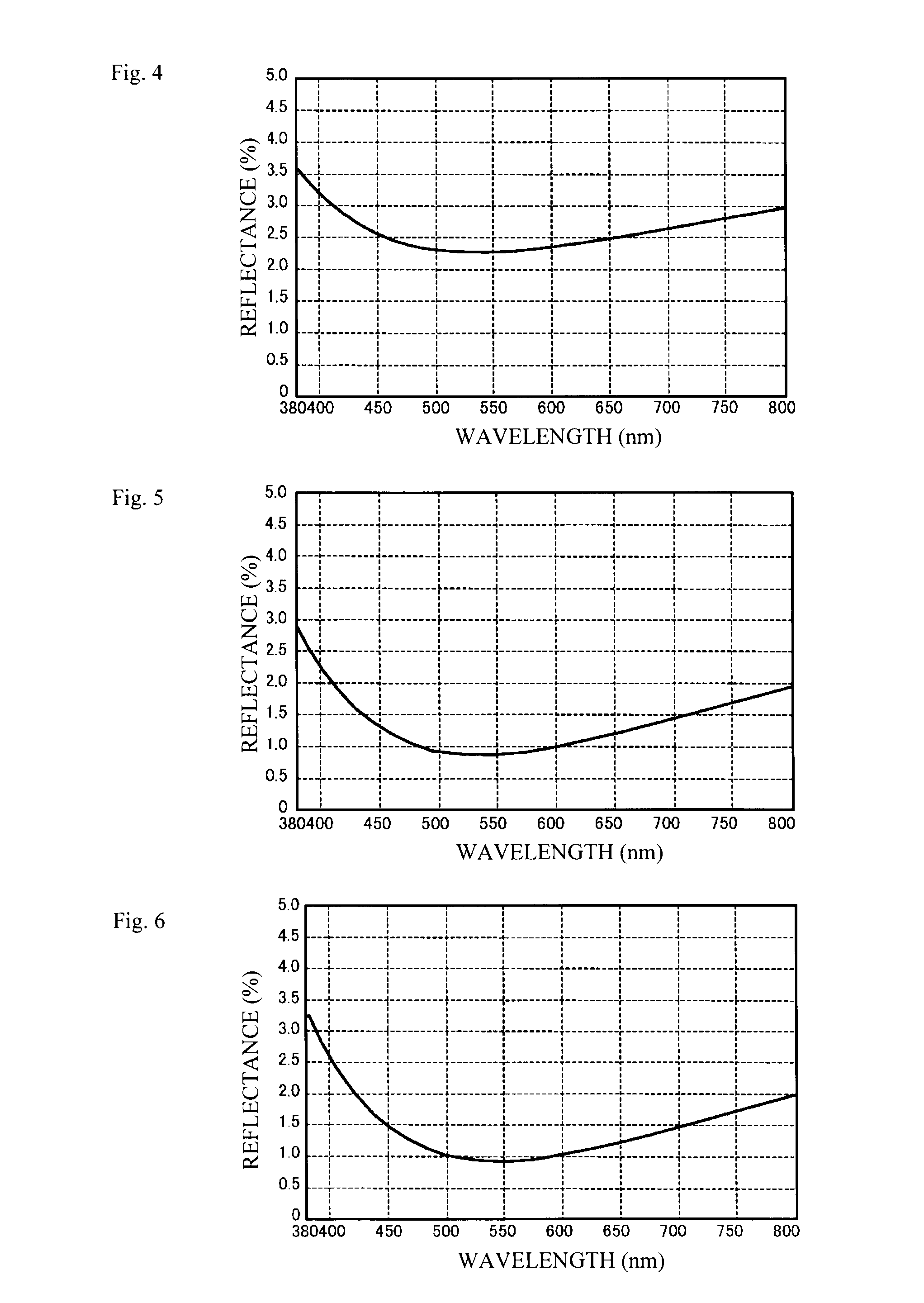
[0118]The constitutions of antireflection films designed so as to bring their characteristics near to the single characteristic and each formed on the surface of the core glass so that the outermost surface layer was formed of silicon dioxide (SiO2) or alumina (Al2O3) are shown in Tables 6 to 8, and the reflection characteristics thereof are shown in FIGS. 5 to 7, respectively. Further, an antireflection film having the constitution shown in Table 6 and having an outermost layer film thickness of 7 nm was also produced (Example 1-2).

TABLE 6Vapor-Deposited MaterialActual Thickness (nm)First LayerMgF284.93Second LayerSiO29.18AIR

TABLE 7Vapor-Deposited MaterialActual Thickness (nm)First LayerMgF282.00Second LayerAl2O38.19AIR

TABLE 8Vapor-Deposited MaterialActual Thickness (nm)First LayerAl2O38.19Second LayerMgF275.17Third LayerSiO218.36AIR

[0119]As shown in FIGS. 5 to 7, the two or more layer film constitutions had small deviations from the single characteristic, compared to monolayer coa...

example 2

Conventional Example 2

[0120]The constitution of an antireflection film in which a conventional multilayer film (7 layers) was formed on the surface of the core glass is shown in Table 9, and the reflection characteristic thereof is shown in FIG. 8. This characteristic is hereinafter called the multi characteristic 7.

TABLE 9Vapor-Deposited MaterialActual Thickness (nm)First LayerAl2O379.24Second LayerOH514.42Third LayerAl2O326.54Fourth LayerOH579.66Fifth LayerAl2O312.82Sixth LaterOH531.71Seventh LayerMgF296.87AIR

Example 4

[0121]The constitution of an antireflection film designed so as to bring its characteristic near to the multi characteristic 7 and formed on a surface of a core glass so that the outermost surface layer was formed of silicon dioxide (SiO2) is shown in Table 10, and the reflection characteristic thereof is shown in FIG. 9. Further, an antireflection film having the constitution shown in Table 10 and having the outermost layer film thickness of 7 nm was also produced (...


PUM

PropertyMeasurementUnit
Thicknessaaaaaaaaaa
Thicknessaaaaaaaaaa
Thicknessaaaaaaaaaa

Abstract

The present invention relates to an optical element comprising: a optical glass made of a phosphate glass or a fluorophosphate glass; and an optically functional film formed on a surface of the optical glass, wherein the optically functional film comprises two or more layers made of different materials, and the outermost surface layer thereof is made of a material(s) having low reactivity with phosphoric acid.

Description

TECHNICAL FIELD[0001]The present invention relates to an optical element improved in environmental durability and a method for producing the same. Particularly, the present invention relates to an optical element suppressed in cloudiness and alteration thereof and improved in environmental durability when a phosphate glass or the like is used as a glass material, and to a method for producing the same.BACKGROUND ART[0002]Recently, attention has been paid to a direct press molding method in which an optical glass element such as a glass lens is press-molded, and which makes it possible to use the molded surface as it is without polishing or the like.[0003]A glass material used in this press molding method is adjusted in composition so that the glass transition temperature thereof decreases, when it is intended to lower the press molding temperature as well as to improve processability. For example, in order to realize a particularly low temperature, it is known that a substantial dec...

Claims


Application Information

Patent Timeline
IPC IPC(8): B32B17/06C03C27/10B05D5/06C03C17/34G02B1/11G02B1/115
CPCC03C17/3417C03C17/3452Y10T428/24777G02B1/113G02B1/115C03C2217/732
Inventor TAKAHASHI, MICHITOMIYAZAKI, SUNAO
Owner ASAHI GLASS CO LTD
Why Eureka
Try Eureka