Power source apparatus for vehicle

a technology for power source equipment and vehicles, applied in the direction of battery/fuel cell control arrangement, electric devices, transportation and packaging, etc., can solve the problems of low durability resistance to frequent charge and discharge, low cost of lead-acid batteries, rapid deterioration of lead-acid batteries, etc., to reduce manufacturing costs and high energy density

Inactive Publication Date: 2011-01-06
DENSO CORP
View PDF17 Cites 152 Cited by
  • Summary
  • Abstract
  • Description
  • Claims
  • Application Information

AI Technical Summary

Benefits of technology

[0012]It is an object of the present invention to provide a power source apparatus which is mounted to vehicles equipped with a high performance battery (or a high energy density battery which serves

Problems solved by technology

The lead-acid battery is cheap in cost when compared with high density energy batteries (high performance batteries) such as nickel batteries and lithium batteries, but has a low durability resistance to frequent charge and discharge.
For example, because a lead-acid battery mounted on a vehicle with idle reduction function (which is a function to automatically stop idling to save and reduce fuel consumption) discharges electric power frequently, this causes a rapid deterioration of the lead-acid battery.
In particular, a lead-acid battery mounted on a vehicle with an alternator capable of regenerating electri

Method used


Image

  • Power source apparatus for vehicle
  • Power source apparatus for vehicle
  • Power source apparatus for vehicle

Examples


first embodiment

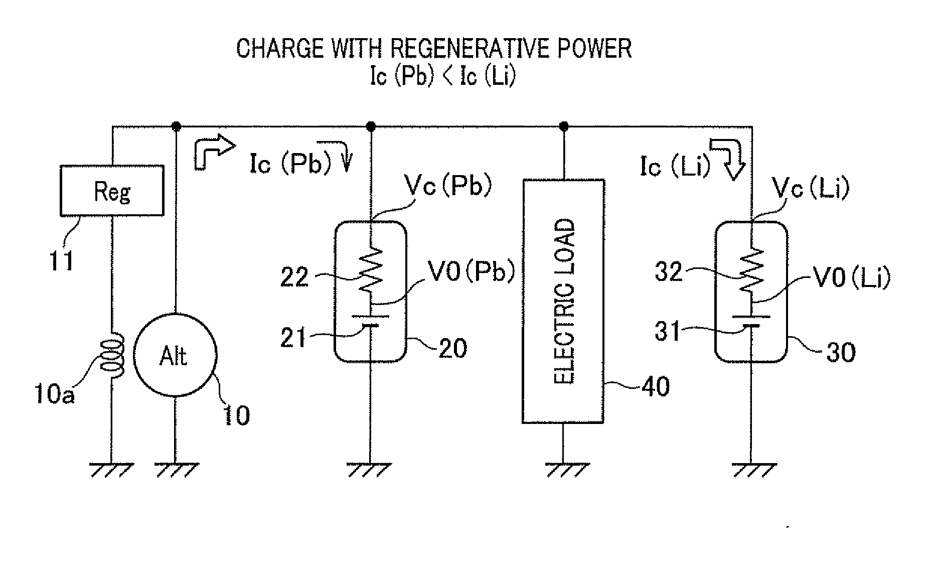
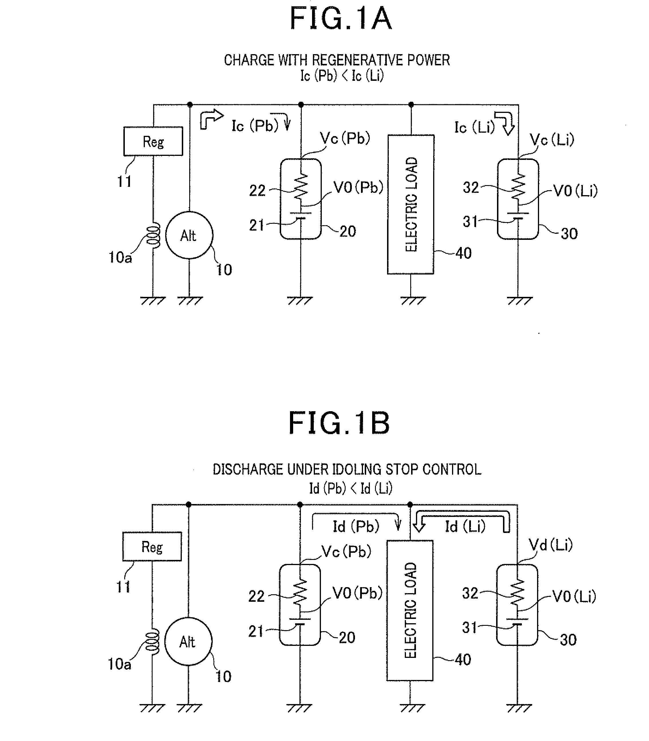
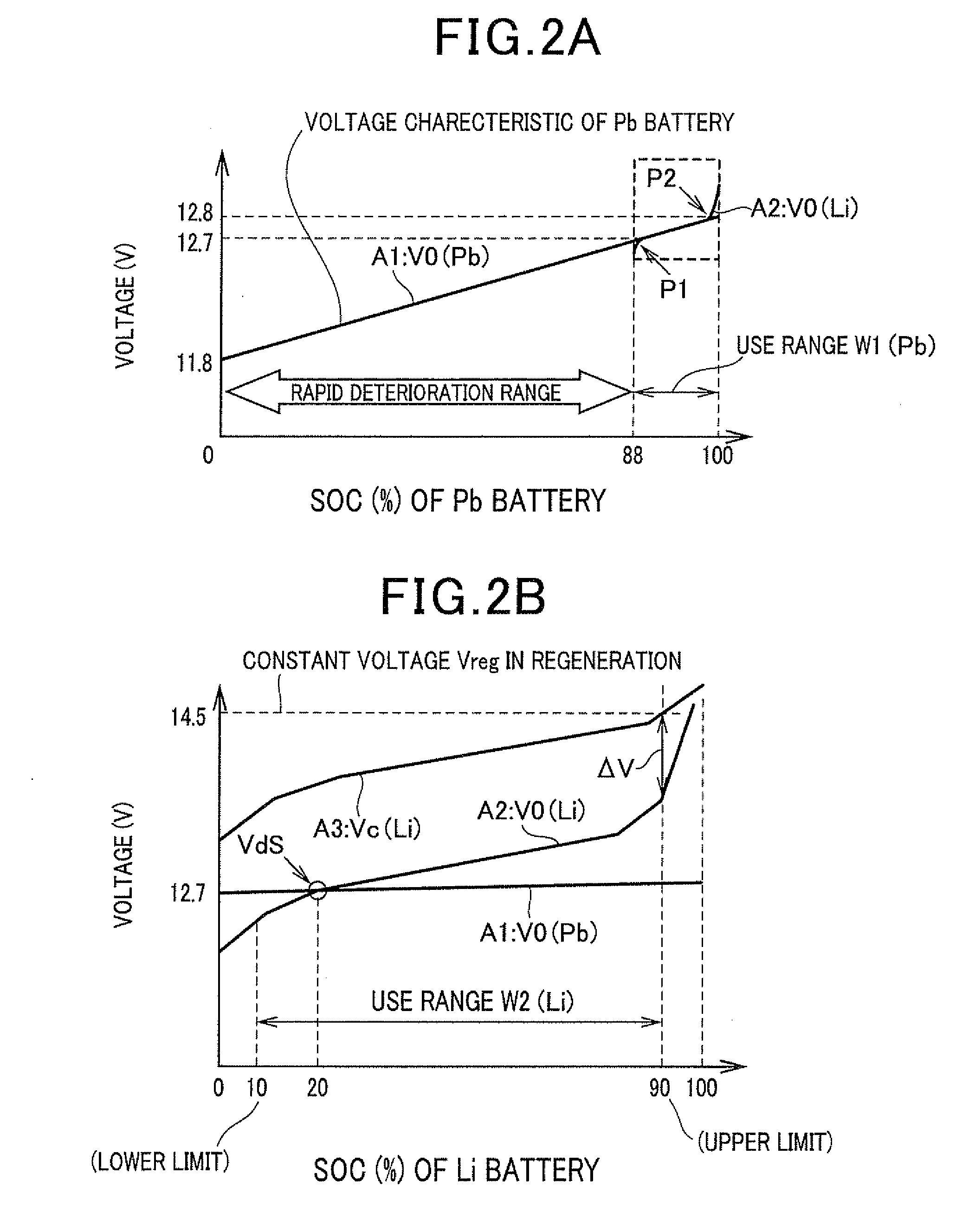
[0069]A description will now be given of the power source apparatus for vehicle according to the first embodiment of the present invention with reference to FIG. 1A, FIG. 1B, FIG. 2A, FIG. 2B, FIG. 3, FIG. 4A, and FIG. 4B.

[0070]The power source apparatus according to the first embodiment can be applied to vehicles with an internal combustion engine. For example, the power source apparatus according to the first embodiment can be applied to various types of vehicles equipped with an idle reduction apparatus. The idle reduction apparatus automatically stops the operation of the internal combustion engine when a predetermined engine stop condition is satisfied, and then automatically restarts the internal combustion engine when a predetermined engine restart condition is satisfied. The idling reduction apparatus will be referred to as the “idle stop apparatus or idle stop function” through the following explanation.

[0071]The vehicle equipped with the power source apparatus according to...

second embodiment

[0111]A description will be given of the power source apparatus according to the second embodiment of the present invention with reference to FIG. 5. FIG. 5 is a block diagram showing a schematic electric circuit of the power source apparatus according to the second embodiment.

[0112]In the structure of the power source apparatus according to the second embodiment shown in FIG. 5, the lithium battery 30 supplies the electric power to electrical loads 43 which require an approximate constant voltage or a voltage which is changed within at least a predetermined voltage range. For example, there are a navigation system and an audio system as the electrical loads 43 mounted to vehicles. When the power source apparatus supplies electric power, a voltage of which is fluctuated, not constant, or changed out from a predetermined allowable range, and when the voltage of the electric power temporarily drops below a minimum operation voltage, the navigation system and / or audio system as the ele...

third embodiment

[0117]A description will be given of the power source apparatus according to the third embodiment of the present invention with reference to FIG. 6. FIG. 6 is a block diagram showing a schematic electric circuit of the power source apparatus according to the third embodiment of the present invention.

[0118]The power source apparatus according to the third embodiment has a protection control means 60 which controls the charging capacity to and discharging capacity from the lithium battery 30 in order to avoid the overcharging to the lithium battery 30 and the over discharging from the lithium battery 30.

[0119]The protection control means 60 always receives detection signals regarding the terminal voltages Vc and Vd or the open circuit voltage V0 (Li) of the lithium battery 30, and a detection signal transferred from a current detection means 61 which detects a current flowing in the lithium battery 30.

[0120]The protection control means 60 instructs the electromagnetic relay 50 to open...


PUM


Abstract

A power source apparatus mounted to a vehicle is equipped with a lead-acid battery and a lithium battery. An open circuit voltage and an internal resistance of each of the batteries are determined to satisfy the following conditions (a1), (a2), and (a3): (a1) In the use range of SOC of the lead-acid battery and the use range of SOC of the lithium battery, there is an equal voltage point Vds at which the open circuit voltage V0 (Pb) of the lead-acid battery becomes equal to the open circuit voltage V0 (Li) of the lithium battery; (a2) The relationship of V0 (Li)>V0 (Pb) is satisfied in the upper limit side of the use range of SOC of the battery; and (a3) A terminal voltage Vc (Li) of the lithium battery is not more than a set voltage Vreg of a regulator when a maximum current flows in the lithium battery.

Description

CROSS-REFERENCE TO RELATED APPLICATION[0001]This application is related to and claims priority from Japanese Patent Applications No. 2009-156947 filed on Jul. 1, 2009 and No. 2009-223947 filed on Sep. 29, 2009, the contents of which are hereby incorporated by reference.BACKGROUND OF THE INVENTION[0002]1. Field of the Invention[0003]The present invention relates to a power source apparatus to be applied to vehicles.[0004]2. Description of the Related Art[0005]A vehicle with an internal combustion engine generally has a lead-acid battery in order to supply electric power to various types of electrical loads such as a starter motor mounted on the vehicle. The lead-acid battery is cheap in cost when compared with high density energy batteries (high performance batteries) such as nickel batteries and lithium batteries, but has a low durability resistance to frequent charge and discharge. For example, because a lead-acid battery mounted on a vehicle with idle reduction function (which is ...

Claims


Application Information

Patent Timeline
IPC IPC(8): B60L1/00B60L50/16
CPCB60R16/033Y02T10/70B60L7/12B60L11/14B60L11/1859B60L11/1866B60L11/1868B60L2210/10B60L2210/30B60L2240/12B60L2240/545B60L2240/547B60L2240/549Y02T10/7077Y02T10/7044Y02T10/7241Y02T10/7066Y02T10/7061Y02T10/7216Y02T10/7016Y02T10/7011B60L11/1861B60L1/00H02J7/0003Y02T10/7005B60L3/0046B60L50/16B60L58/14B60L58/22B60L58/20B60L58/15B60L58/21B60L58/13B60L58/24Y02T10/72Y02T10/7072H02J1/10
Inventor TAMURA, HIROSHIKAMEOKA, TERUHIKOSUENAGA, TAKAOIMAI, ATSUSHISAITO, SHIGENORI
Owner DENSO CORP
Why Eureka
Try Eureka