Carbon Microbeads with Hierarchical Structure

a technology of carbon microbeads and hierarchical structures, applied in the field of carbon microbeads, can solve the problems of prone to deterioration low application performance of graphitic carbon microbeads made by high temperature treatment (htt) of mcmbs, and low cost, and achieve the effect of simple and inexpensiv

Inactive Publication Date: 2011-01-27
WISYS TECH FOUND
View PDF6 Cites 36 Cited by
  • Summary
  • Abstract
  • Description
  • Claims
  • Application Information

AI Technical Summary

Benefits of technology

[0026]Yet another aspect of this invention is to provide a relatively simple and inexpensive method for producing hierarchically-structured carbon microbeads. In particular, in one embodiment the present invention provides a low-cost process for converting biomass, and in particular sugars and starches, to carbon microbeads containing graphite nanocrystals.

Problems solved by technology

A major problem with these materials is that they are relatively expensive due to complex manufacturing processes and high processing temperatures (2000-3000° C.) required for graphitization.
Graphitic carbon microbeads made by high temperature treatment (HTT) of MCMBs do not perform well in some applications, such as anodes for Li-ion batteries.
In this application, the graphitic carbon microbeads are prone to deterioration as the graphitic lamina flake off due to stresses caused by size changes that accompany charge / discharge processes.

Method used


Image

  • Carbon Microbeads with Hierarchical Structure
  • Carbon Microbeads with Hierarchical Structure
  • Carbon Microbeads with Hierarchical Structure

Examples


example 1

[0074]A 50 mL beaker was charged with 1.40 g corn starch (Argo), 0.50 g Ni(NO3)2.6H2O and 20 mL of room-temperature deionized water. The mixture was heated on a hot plate while stirring with a glass stir rod until a viscous gel formed. 13.03 grams of this gel was transferred to a PTFE cup (23 mL capacity), which was then sealed into a pressure vessel (Parr model 4749), which was then placed in a 200° C. oven. After three days in the oven, the pressure vessel was removed and allowed to cool naturally to below 100° C. The vessel was opened revealing a yellowish liquid and dark (brown-black) solid residues. The liquid was decanted, and the solids were washed with a small amount of deionized water. Residual water was removed by heating the sample at 60° C. in a vacuum oven. The isolated yield of the product was 0.26 grams (Product CS / Ni-HT)

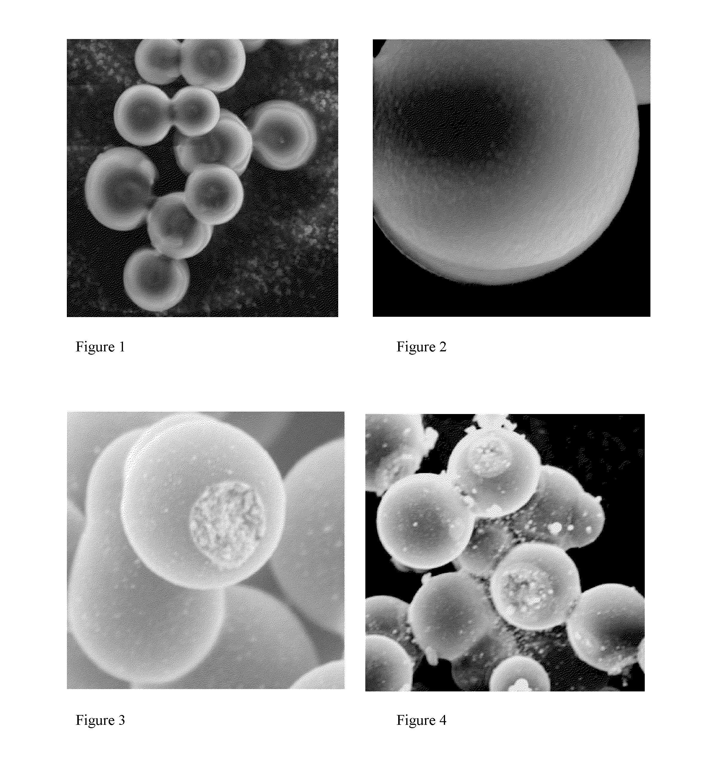
[0075]Examination of this product using scanning electron microscopy (SEM) revealed microspheres that were typically 5-25μ in size, and which had an ...

examples 2-6

[0077]The process described in Example 1 was repeated, except that other polysaccharides or sugar were substituted for corn starch. Except for microbead size and polydipersity, the products were generally similar to CS / Ni-HT. Table 1 gives a summary of starting materials used and relative particle size and polydispersity:

TABLE 1ExampleStarting materialSample IDSize and polydispersity relative to CS-HTExample 1Corn strachCS / Ni-HT—Example 2Wheat starchWS / Ni-HTAbout the same size and polydispersity.Example 3SucroseSC / Ni-HTAbout the same size and polydispersity.Example 4DextranDT / Ni-HTAbout the same size; slightly higher polydispersity.Example 5Rice starchRS / Ni-HTSmaller microbeads; about the same polydispersity.Example 6Potato starchPS / Ni-HTMicrobeads generally smaller, high polydisperisty.

example 7

[0078]An alumina boat was charged with 0.2553 grams of the product made in Example 1 (CS / Ni-HT). The boat containing the sample placed in a tube furnace, which was purged with dry Ar. The sample was heated, under flowing Ar, at a rate of 10° C. / min to 850° C., and held at that temperature for 4 hours. The sample was then allowed to cool naturally to room temperature, and was then removed from the furnace. The yield of the product (CS / Ni-HT-85) was 0.1418 grams (44.5% weight loss).

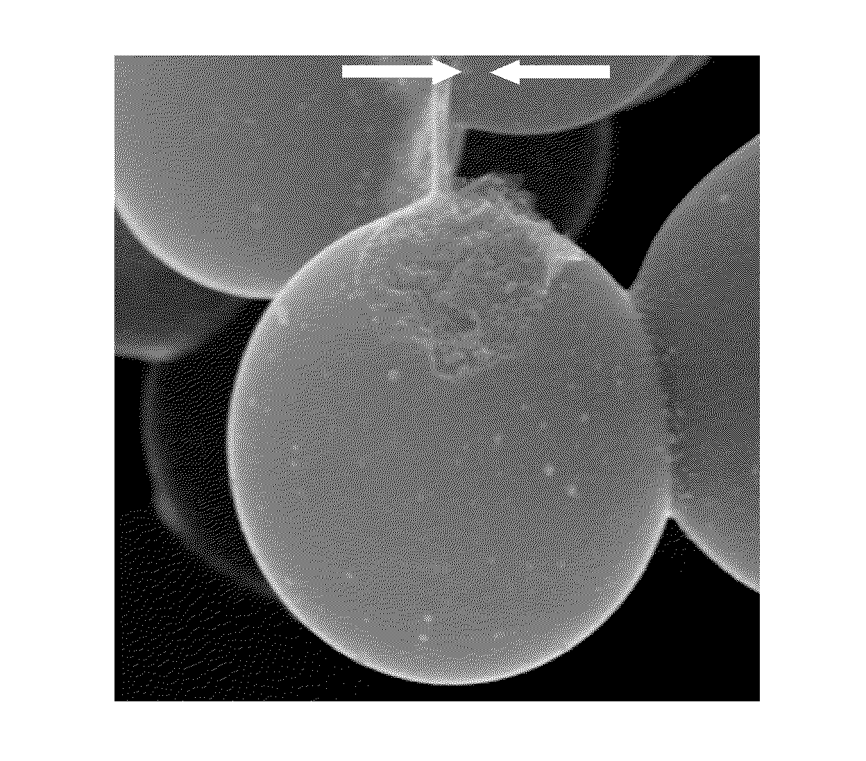
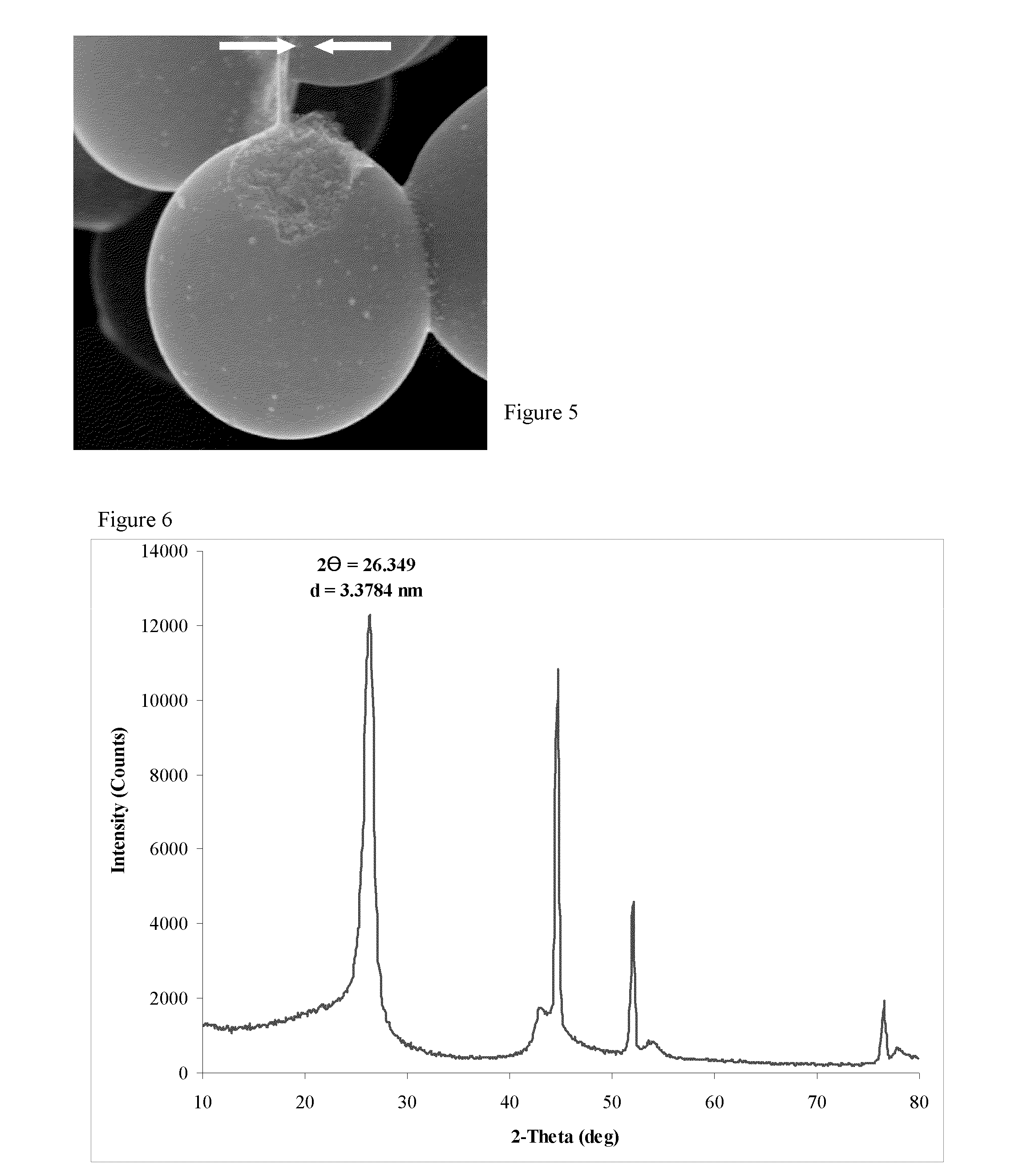
[0079]Examination of the product by SEM revealed that the product contained microbeads that were ca. 5-25μ in size, and which were covered with a relatively smooth coating that was open in one or (at most) a few places (FIGS. 3 and 4). These openings revealed that the microbeads had a core / shell microstructure, that the core had a nanostructure corresponding to a non-laminar aggregated of platelet like nanoparticles, and that the shell was relatively thin. We noted that, in some cases, a portion of the shel...


PUM

PropertyMeasurementUnit
diameteraaaaaaaaaa
diameteraaaaaaaaaa
degree of crystallinityaaaaaaaaaa

Abstract

The preset invention is a hierarchically-structured carbon microbead and method for forming the microbead utilizing hydrothermal carbonization of a biomass / catalyst mixture to produce partially carbonized amorphous microspheres, wherein the biomass is an inexpensive material containing a high oxygen content component (e.g., sugar, starch, alcohol), and the catalyst is a metal or metal-containing compound, preferably a transition metal compound, and more specifically a transition metal selected from Fe, Co, Ni, Ru, Rh, Pd, Os, Ir, and Pt. Subsequently, a heat treatment is performed where the amorphous microspheres are heated to a temperature that is sufficiently high so as to result in carbonization, graphitization, and production of a carbonaceous coating or shell on the core of the microbead.

Description

CROSS REFERENCE TO RELATED APPLICATION[0001]This application claims the benefit of U.S. Provisional Patent Application Ser. No. 61 / 227,501 filed Jul. 22, 2009 hereby incorporated by reference herein in its entirety.FIELD OF THE INVENTION[0002]The present invention relates to carbon microbeads with a novel and useful hierarchical structure. More particularly, the present invention relates to carbon microbeads comprising graphitic nanoparticles that are encapsulated by a thin smooth shell, and a method for making the same.BACKGROUND OF THE INVENTION[0003]The structure of materials can be classified by the general magnitude of various features being considered. The most common major classifications of structure:[0004]Bulk structure refers to the overall appearance of a large sample of the material.[0005]Macroscale structure, which includes features that can be seen with the naked eye, refers to structural features greater than about 0.1 mm in size.[0006]Microscale structure refers to s...

Claims


Application Information

Patent Timeline
Patent Type & Authority Applications(United States)
IPC IPC(8): H01B5/00B32B15/02B32B9/04C01B31/08B29B9/12B82Y30/00
CPCB01J20/20B01J20/28004B01J20/324B01J20/3293Y10T428/2989C01B31/04Y02C10/08B01D2253/102B01D2253/304C01B31/02C01B32/05Y10T428/249921C01B32/21Y02C20/40
Inventor GIBSON, CHARLES P.KARTHIKEYAN, ANNAMALAI
Owner WISYS TECH FOUND
Why Eureka
Try Eureka