
Method of producing composite magnetic material and composite magnetic material

a technology of composite magnetic materials and magnetic materials, applied in the direction of magnetic bodies, inductances, transportation and packaging, etc., can solve the problems of low insulation property, low withstand voltage and achieve high withstand voltage, high insulation property, and impaired magnetic permeability or core loss

Inactive Publication Date: 2011-02-03
TOHO ZINC
View PDF10 Cites 31 Cited by
  • Summary
  • Abstract
  • Description
  • Claims
  • Application Information

AI Technical Summary

Benefits of technology

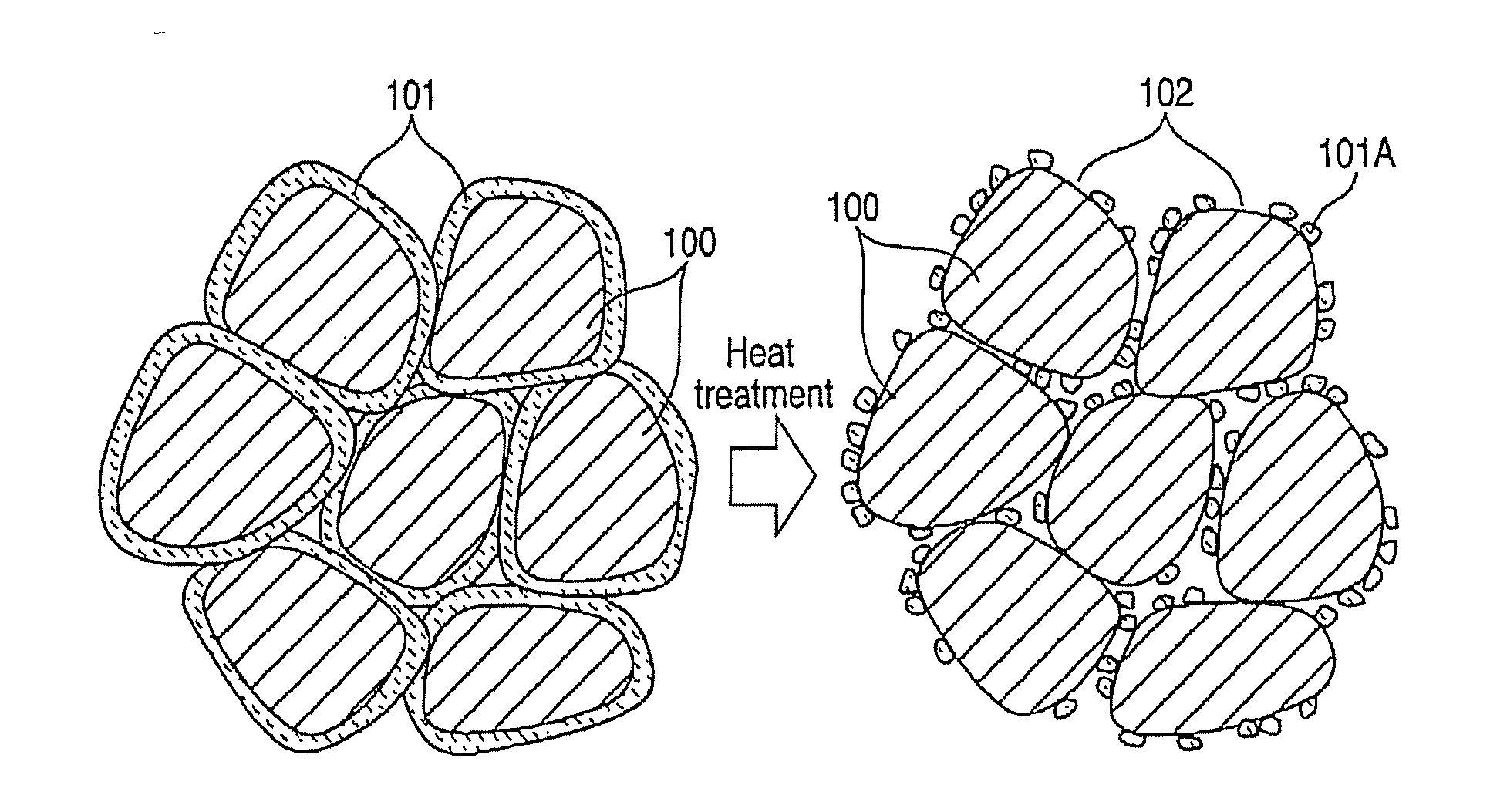
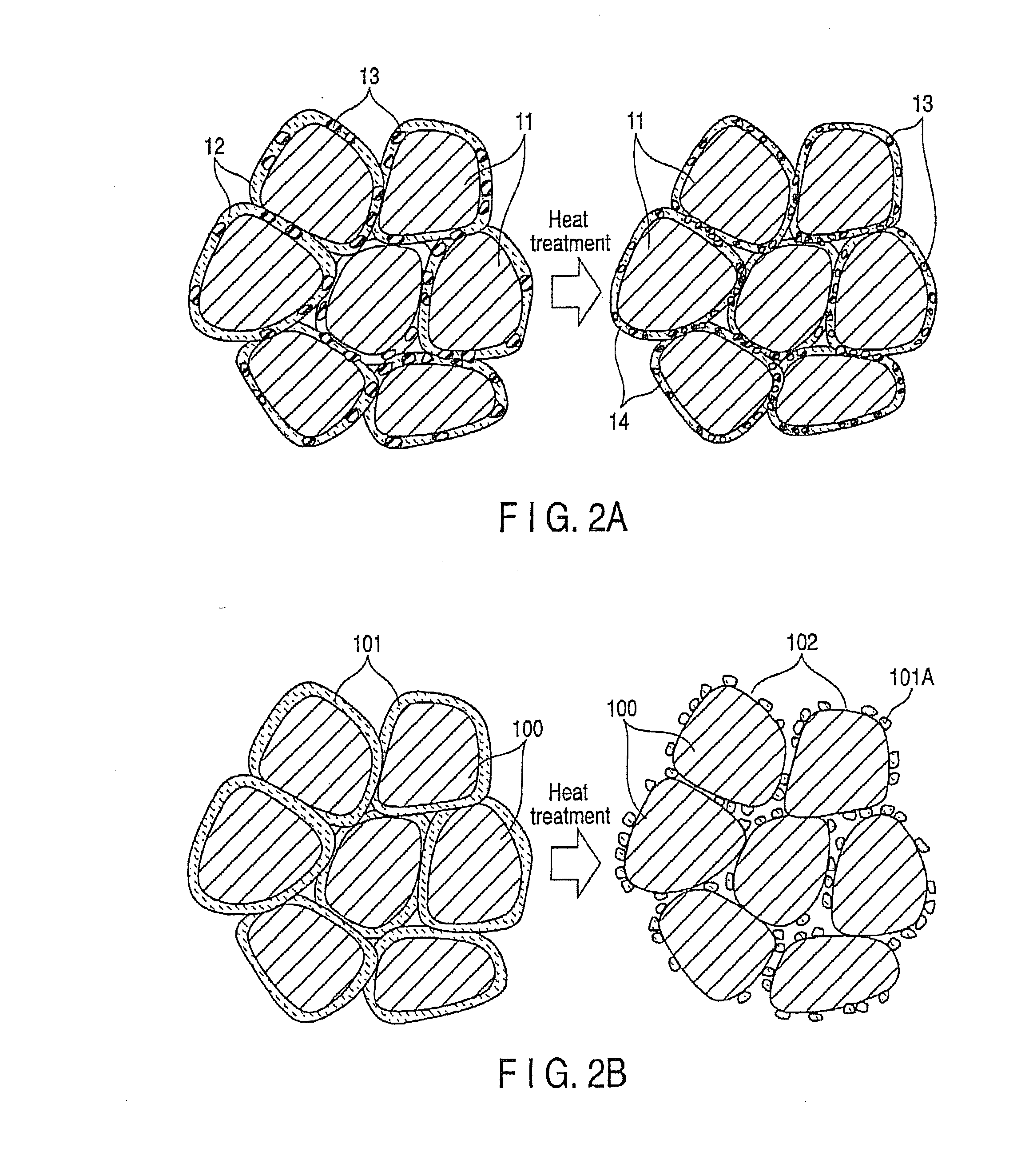
"The present invention provides a method for producing a composite magnetic material with high magnetic permeability and low core loss while maintaining high insulation property and withstand voltage. The method involves adding a layered compound having an insulation property to soft magnetic metal powder to form an insulating layer on the surface of the soft magnetic metal powder by heat treatment. The resulting composite magnetic material has improved magnetic characteristics and can be used for an inductor without the need for a separate case or bobbin, leading to miniaturization of the inductor."

Problems solved by technology

When the addition amount of non-magnetic binders is simply increased to ensure a high insulation property and high withstand voltage, the insulating layer formed on the surface of soft magnetic metal powder becomes thick, and as a result, magnetic characteristics such as magnetic permeability or core loss are impaired.
On the other hand, when the addition amount of non-magnetic binders is lowered, magnetic permeability may be increased but an insulating layer cannot be formed so as to wrap around the surface of soft magnetic metal powders, and as a result, a low insulation property and low withstand voltage are obtained.

Method used


Image

  • Method of producing composite magnetic material and composite magnetic material
  • Method of producing composite magnetic material and composite magnetic material
  • Method of producing composite magnetic material and composite magnetic material

Examples


example 1

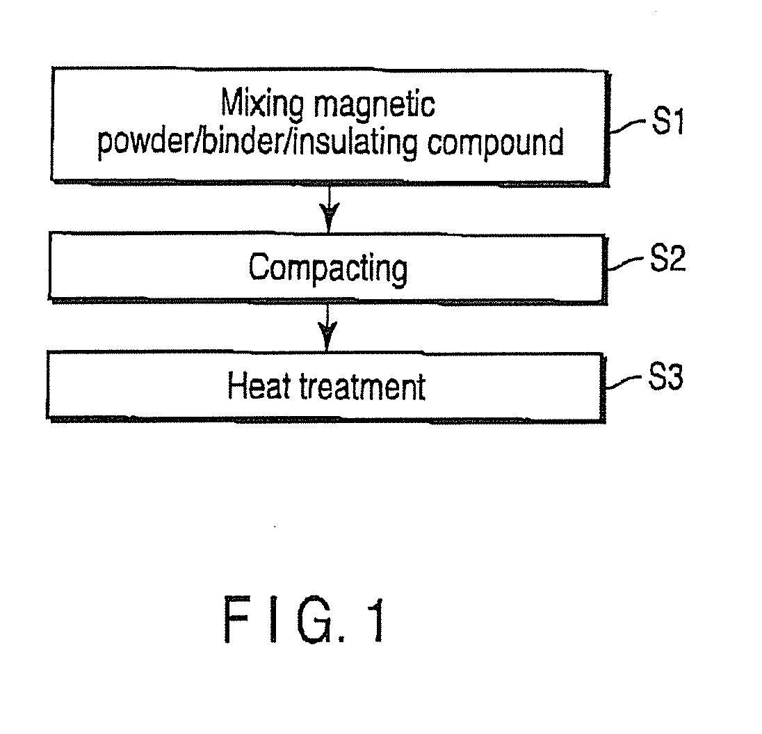
[0049]So-called sendust alloy having composition of Fe,Si-9.5% by mass, and Al-5.5% by mass was prepared by vacuum dissolution method, and with a mechanical alloying, alloy powders having an average particle diameter of about 80 μm were obtained. A layered compound having an insulation property and a non-magnetic binder were added in an amount of 0.5% by mass and 1.0% by mass, respectively, compared to the alloy powders. By using methyl ethyl ketone, wet mixing was carried out, and then mixed powders were obtained by granulation under heating and drying. In this regard, the layered compound having an insulation property and the non-magnetic binder were talc and a silicone resin, respectively. By using the mixed powders obtained, compression compacting was carried with pressure of 1.8 GPa to produce a toroidal core having an outer diameter of 13.4 mm, an inner diameter of 7.7 mm and thickness of 5.5 mm. After that, the core was heat-treated in air at 750° C. for 1 hour to prepare the...

example 2

[0056]To the alloy powders having Fe,Si-9.5% by mass, and Al-5.5% by mass, which is the same composition as Example 1, an insulating layered compound and water glass as a binder were added, followed by wet-kneading with water. According to granulation under heating and drying, mixed powders were produced and the toroidal core which is identical to the Example 1 was produced. As an insulating layered compound, three kinds including bentonite, talc and mica were used. For each of these three kinds of an insulating layered compound, Sample Nos. 11 to 16 were produced (i.e., two for each compound), which are taken as Examples 2-1, 2-2, 2-3, 2-4, 2-5 and 2-6. Montmorillonite was included in the bentonite used. In addition, mica was finely pulverized using a pestle and mortar and then used. The toroidal core produced was subjected to the heat treatment by which it was maintained in air for 1 hour at temperature of 400° C. and 750° C., respectively. After that, the same test as Example 1 w...

reference examples 2 and 3

[0057]As Reference examples 2 and 3, samples of Sample Nos. 9 and 10 were prepared in which no insulating layered compound is added. After that, according to the same test as Example 1, evaluation was carried out. The results are shown in Table 2.

TABLE 2Temperaturefor heatElectricalWithstandSampleInsulatingtreatmentresistancevoltageMagneticCore lossNo.Divisionadditive(° C.)(Ω· m)(V)permeability(kW / m3) 9Reference—4004—463000example 210Reference—7507—601054example 311Example 2-1Bentonite4001.5 × 1044237408012Example 2-2Bentonite7502.3 × 10643.557135513Example 2-3Talc4001.0 × 10451.235395014Example 2-4Talc7501.8 × 10653.955115215Example 2-5Mica4002.9 × 1044536401016Example 2-6Mica7509.5 × 10545.8561221

[0058]As it is evident from Table 2, when only water glass was used, the electrical resistance was low and withstand voltage was not obtained. However, by adding an insulating layered compound, a desired insulation property and withstand voltage are attained, and as a result, it is excell...


PUM

PropertyMeasurementUnit
voltageaaaaaaaaaa
withstand voltageaaaaaaaaaa
temperatureaaaaaaaaaa

Abstract

In one embodiment, a method is disclosed for producing a composite magnetic material, wherein the non-magnetic binder comprises a layered compound having an insulation property and the non-magnetic binder and soft magnetic metal powder is admixed with each other, the admixture is compacted to a desired shape, and the compact is heat-treated under predetermined condition to form a thin insulating layer made of the insulating layered compound on the surface of the soft magnetic metal powder, thereby producing the composite magnetic material having a withstand voltage of 20 V or more.

Description

CROSS REFERENCE TO RELATED APPLICATIONS[0001]This is a Continuation Application of PCT Application No. PCT / JP2009 / 057452, filed Apr. 13, 2009, which was published under PCT Article 21(2) in Japanese.[0002]This application is based upon and claims the benefit of priority from prior Japanese Patent Application No. 2008-106048, filed Apr. 15, 2008, the entire contents of which are incorporated herein by reference.BACKGROUND OF THE INVENTION[0003]1. Field of the Invention[0004]The present invention relates to a method of producing an inductor that is wire-wound to a metal-based soft magnetic alloy composite material applied for a power circuit of an electronic component, etc., and more particularly to, a method of producing a composite magnetic material such as dust core used as a core excellent in magnetic characteristics, and a composite magnetic material that is prepared by using the method.[0005]2. Description of the Related Art[0006]In recent years, along with needs for miniaturiza...

Claims


Application Information

Patent Timeline
Patent Type & Authority Applications(United States)
IPC IPC(8): H01F1/26H01F1/04B22F1/08B22F1/16
CPCB22F1/02C22C38/08C22C38/00H01F1/24H01F1/33H01F17/043H01F17/062H01F41/0246B22F2998/10C22C38/06C22C38/02B22F1/007B22F3/02B22F2003/248B22F1/16B22F1/08B22F1/105
Inventor OTSUKI, ETSUONAKANO, SHINYAKUROSAKI, HIROFUMI
Owner TOHO ZINC
Learn More