Antireflection film, polarizing plate and image display device

Inactive Publication Date: 2011-02-03
FUJIFILM CORP
View PDF21 Cites 7 Cited by
  • Summary
  • Abstract
  • Description
  • Claims
  • Application Information

AI Technical Summary

Benefits of technology

[0017]According to the invention, it is possible to provide an antireflection film which has excellent antireflection properties, antistatic properties, scar resistance, adhesion and antifouling properties and which is excellent in productivity.
[0018]Also, it is possible to pr

Problems solved by technology

According to this method, it is necessary to newly provide a layer other than the low refractive index layer, and there is involved such a problem that loads of equipment and time are large so that the productivity is inferior.
When the refractive index of the antistatic layer is high, in an optical film, there is caused such a problem that non-intended interference unevenness is caused due to a difference in a refractive index from an adjacent layer, or a color tint of the reflected color becomes strong.
However, the materials specifically disclosed in the working examples of JP-A-2007-185824, JP-A-2005-316425 and JP-A-2007-293325 are an ion-conducting material, and there was the case where the conductivity is not always sufficient depending upon the environmental moisture.
However, in the case where such a compound is merely introduced into a low refractive in

Method used


Image

  • Antireflection film, polarizing plate and image display device
  • Antireflection film, polarizing plate and image display device
  • Antireflection film, polarizing plate and image display device

Examples


preparation example 1

[0283]8.0 g of 3,4-ethylenedioxythiophene was added to 1,000 mL of a 2% by mass aqueous solution of polystyrenesulfonic acid (molecular weight: about 100,000) (PS-5, manufactured by Tosoh Organic Chemical Co., Ltd.) and mixed at 20° C. After 100 mL of an oxidation catalyst liquid (containing 15% by mass of ammonium persulfate and 4.0% by mass of ferric sulfate) was added to this mixed liquid, the mixture was allowed to react while stirring at 20° C. for 3 hours.

[0284]After 1,000 mL of ion-exchanged water was added to the resulting reaction liquid, about 1,000 mL of the solution was removed by adopting an ultrafiltration method. This operation was repeated thrice.

[0285]100 mL of a sulfuric acid aqueous solution (10% by mass) and 1,000 mL of ion-exchanged water were added to the resulting solution, and about 1,000 mL of the solution was removed by adopting an ultrafiltration method.

[0286]After 1,000 mL of ion-exchange water was added to the resulting liquid, about 1,000 mL of the liqu...

preparation example 2

[0289]After 200 mL of acetone was added to 200 mL of the conductive polymer composition (B-1) prepared in Preparation Example 1, 210 mL of water and acetone were removed by ultrafiltration. This operation was repeated once, and a solids concentration was regulated with acetone to form a 1.0% by mass (at 20° C.) water / acetone solution. There was thus prepared a conductive polymer composition (B-2). This solution had a water content of 15% by mass, and the water / acetone mixed solvent had a relative dielectric constant of 30.3.

preparation example 3

[0290]After 500 mL of acetone having 2.0 g of trioctylamine dissolved therein was added to 200 mL of the conductive polymer composition (B-2) prepared in Preparation Example 2, the mixture was stirred by a stirrer for 3 hours. 510 mL of water and acetone were removed by ultrafiltration. A solids concentration was regulated with acetone to form a 1.0% by mass (at 20° C.) water / acetone solution. There was thus prepared a conductive polymer composition (B-3). This solution had a water content of 2% by mass, and the water / acetone mixed solvent had a relative dielectric constant of 22.7.


PUM

PropertyMeasurementUnit
Currentaaaaaaaaaa
Particle sizeaaaaaaaaaa

Abstract

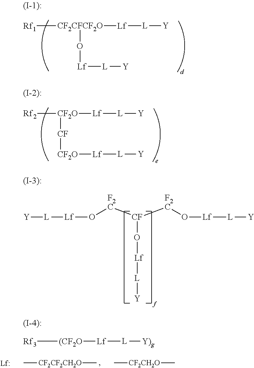
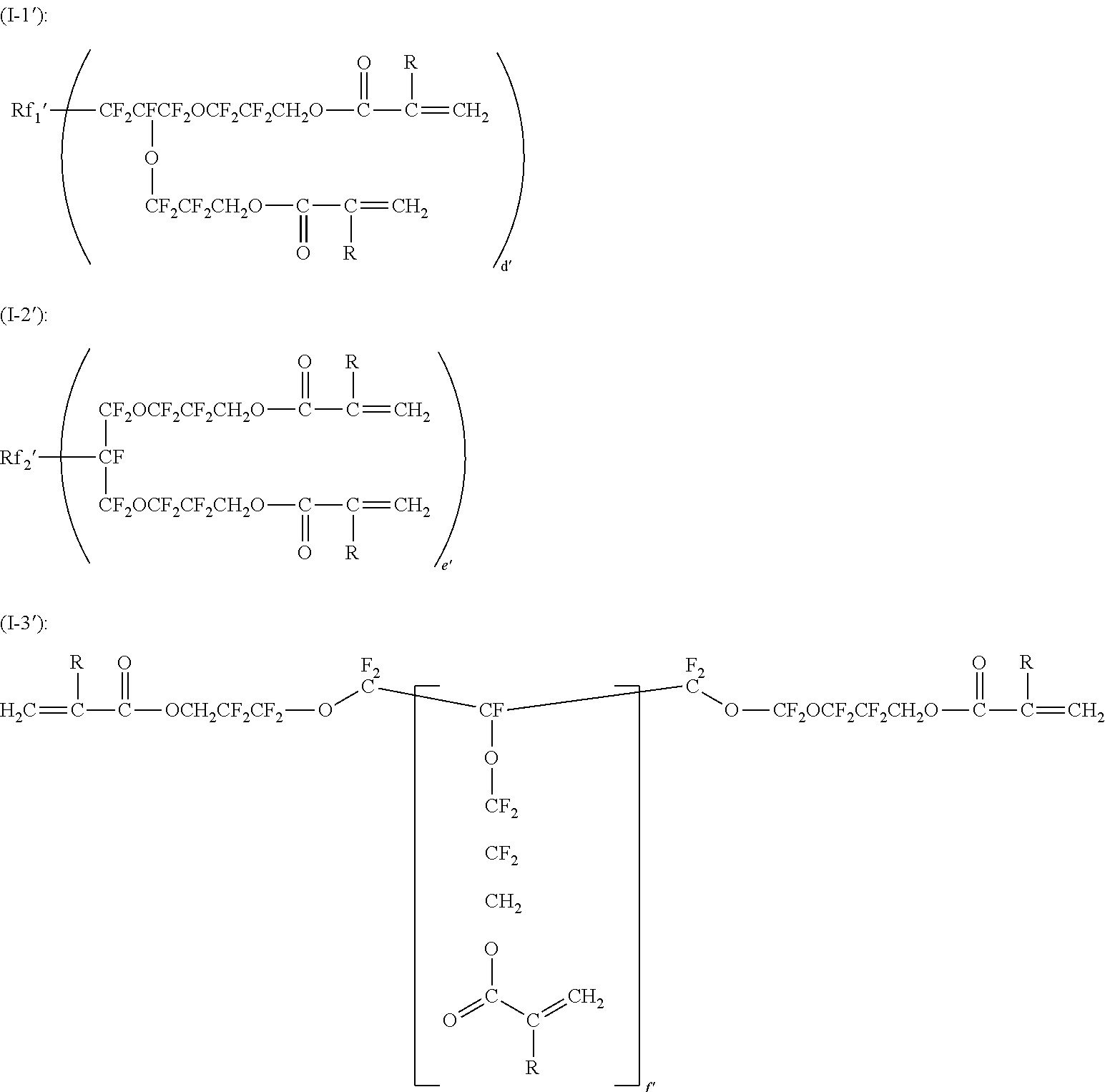
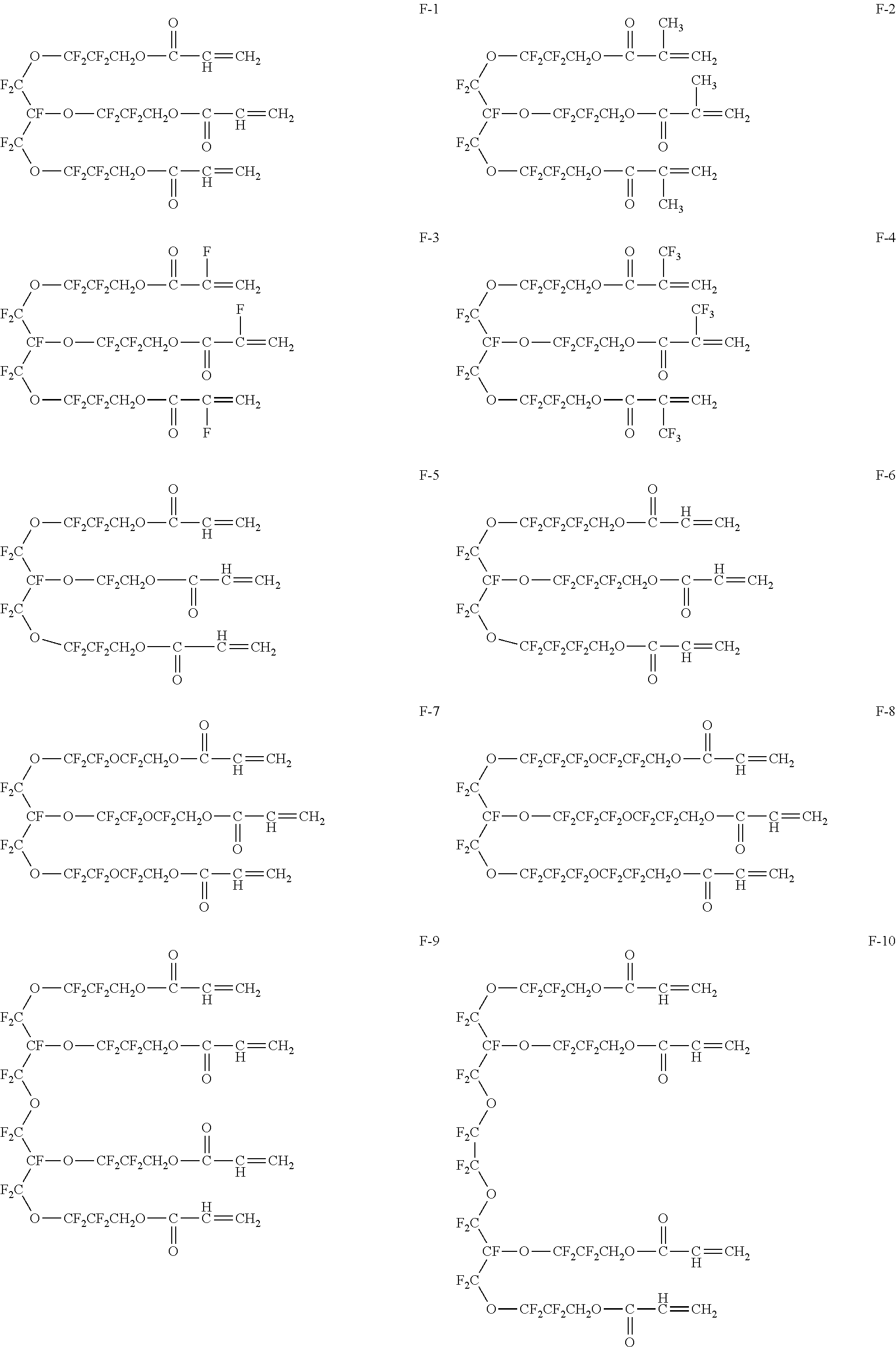
An antireflection film includes a support and a low refractive index layer formed from a composition for low refractive index layer containing (A) a polyfunctional fluorine-containing monomer having a polymerizable group and (B) a hydrophobilized conductive polymer composition containing a π-conjugated system conductive polymer and an anion group-containing polymer dopant, and a common logarithm log(SR) of a surface resistivity SR (Ω/sq) of a surface of the antireflection film on a side at which the low refractive index layer is provided is not more than 13.0.

Description

FIELD OF THE INVENTION[0001]The present invention relates to an antireflection film, a polarizing plate and an image display device. In more detail, the invention relates to an antireflection film having high antistatic properties and antireflection properties, a polarizing plate using the subject antireflection film and an image display device using the subject antireflection film or the subject polarizing plate for the outermost surface of a display.BACKGROUND OF THE INVENTION[0002]In general, in images display devices such as a cathode ray tube display device (CRT), a plasma display panel (PDP), an electroluminescent display (ELD) and a liquid crystal display device (LCD), for the purpose of preventing a lowering of contrast to be caused due to reflection of external light or reflection of an image, an antireflection film is disposed on the outermost surface of a display, thereby reducing a reflectance by utilizing a principle of optical interference.[0003]In general, the antiref...

Claims


Application Information

Patent Timeline
IPC IPC(8): G02B1/11B32B27/28B32B27/20
CPCB32B23/08B32B23/20B32B27/06B32B27/28Y10T428/25G02B5/0825C08J7/18C08J2365/00C08J2323/06B32B27/08B32B27/16B32B27/18B32B27/281B32B27/302B32B27/306B32B27/308B32B27/32B32B27/34B32B27/36B32B27/365B32B2250/24B32B2264/102B32B2270/00B32B2307/202B32B2307/21B32B2307/40B32B2307/412B32B2307/584B32B2457/20Y10T428/249974Y10T428/3154Y10T428/31533Y10T428/249971
Inventor TAKADA, KATSUYUKIYONEYAMA, HIROYUKISUZUKI, MASAAKI
Owner FUJIFILM CORP
Why Eureka
Try Eureka