

Solar to electric energy conversion device
a technology of solar energy and conversion device, which is applied in the direction of electrolytic capacitor manufacture, final product manufacturing, sustainable manufacturing/processing, etc., can solve the problems of low efficiency, failure to achieve liquid-semiconductor hetero junction cells, and successful approaches to improve efficiency
- Summary
- Abstract
- Description
- Claims
- Application Information
AI Technical Summary
Benefits of technology
Problems solved by technology
Method used
Image

Examples
example 1
Fabrication of the Dye-Sensitized Solar Cell 1
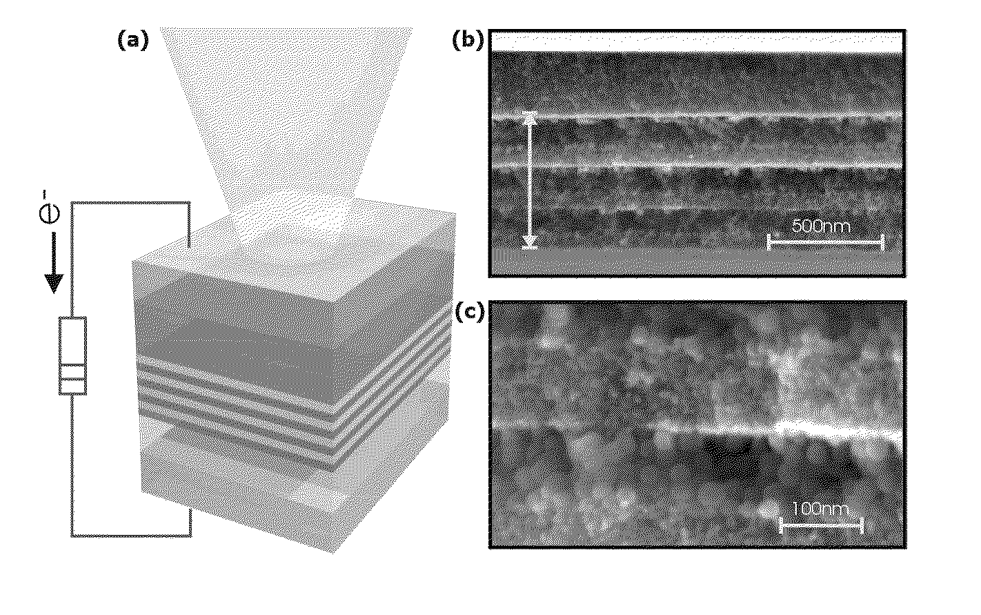
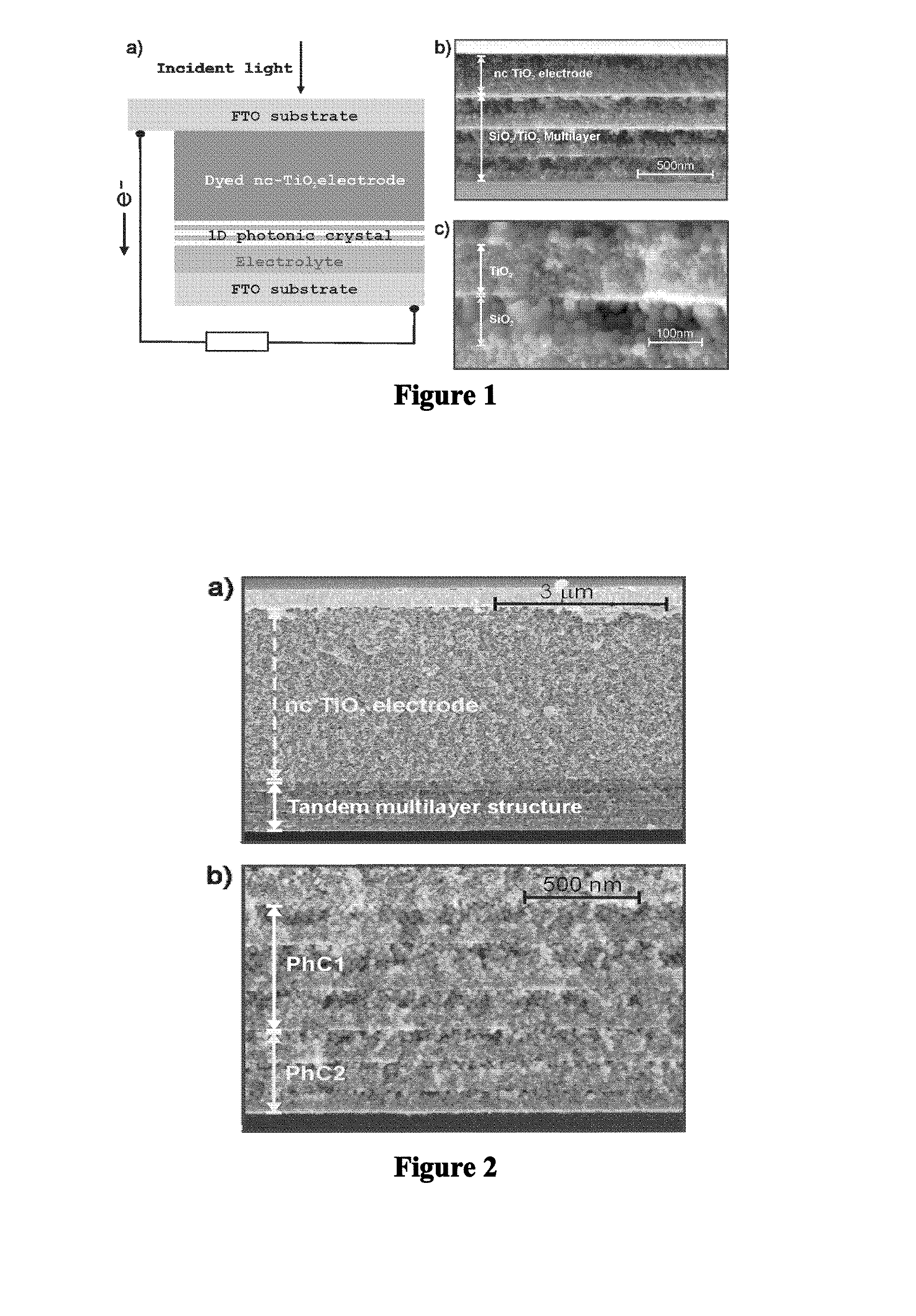
[0082]Dye-Sensitized Solar Cell Coupled to a 1-Dimensional Photonic Crystal with Lattice Parameter of 180±10 nm (95±5 nm SiO2-85±5 nm nc-TiO2) Presenting its Reflectance Maximum at 600 nm
[0083]A 350 nm thick transparent titanium dioxide electrode is deposited by doctor-blading onto a previously cleaned 25 mm×25 mm conducting substrate (fluorine-doped SnO2 conducting glass, Hartford Glass). The anatase particle paste the electrodes are made of was purchased from Solaronix (Ti-Nanoxide HT, Solaronix). The TiO2 layer coated glass so prepared is heated to 450° C. during 30 minutes under oxygen for sintering. On the other hand, nanocrystalline TiO2 particles are synthesised by using a procedure reported by Burnside et al, based on the hydrolysis of titanium isopropoxide followed by a peptization process under hydrothermal conditions. In our case, 20 ml of titanium isopropoxide (97% Aldrich) are added to 36 ml of Milli-Q water and stirred for ...
example 2
Fabrication of the Dye-Sensitized Solar Cell 2
[0084]Dye-Sensitized Solar Cell Coupled to a 1-Dimensional Photonic Crystal with Lattice Parameter of 140±10 nm (55±5 nm SiO2-85±5 nm nc-TiO2) Presenting its Reflectance Maximum at 450 nm
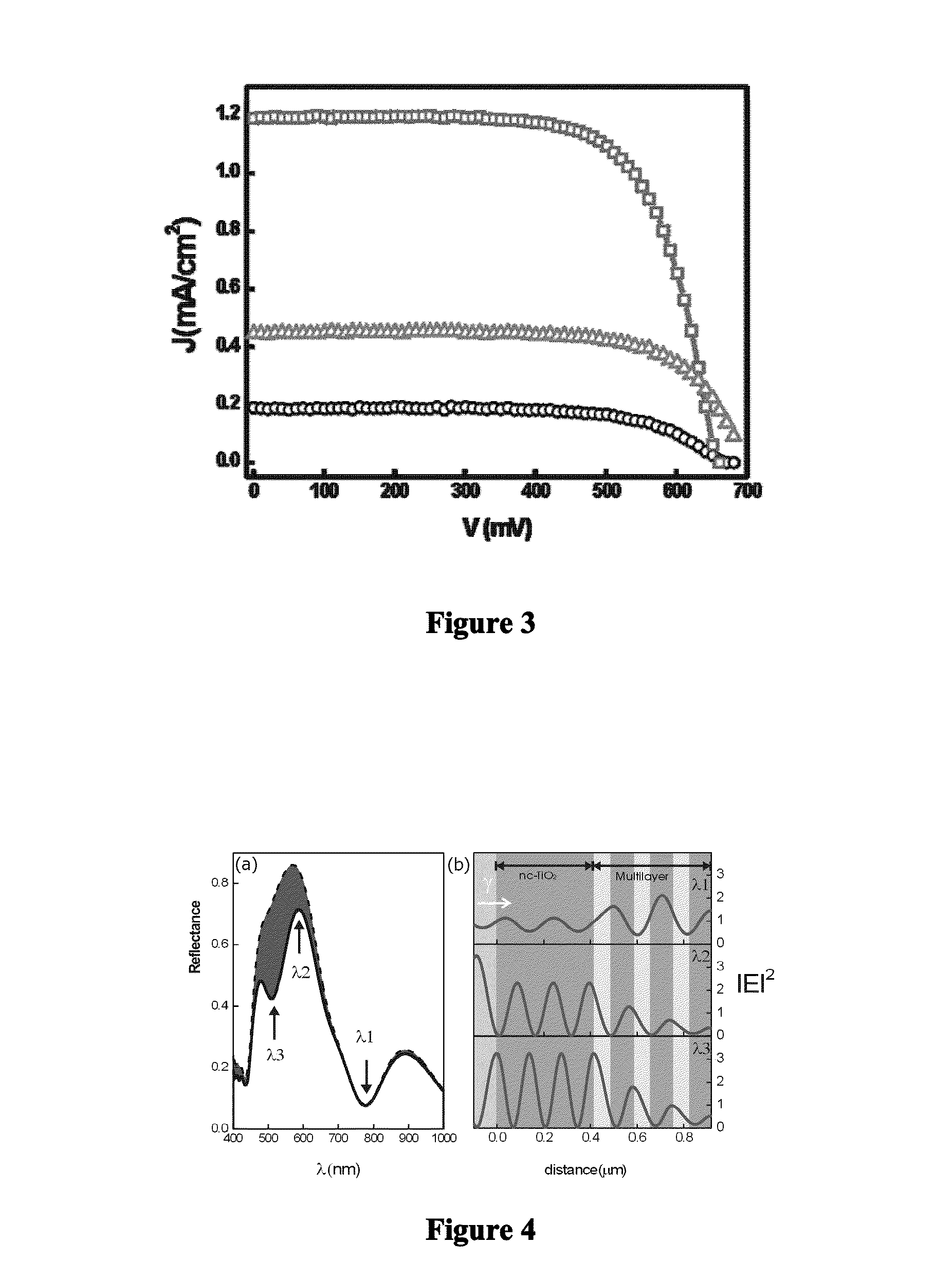
[0085]The same fabrication procedure mentioned in Example 1 is employed to build the dye-sensitized solar cell 2. In this case, the six layer periodic stack is made from silica (2 wt. % precursor solution) and titania (5 wt. % precursor solution) nanoparticles. The precursor suspensions for the spin-coating process are obtained by suspending TiO2 or SiO2 nanoparticles in a mixture of water (21 vol. %) and methanol (79 vol. %), and the rotation speed is kept at 100 rps during the spin-coating process. The IV curve corresponding to this dye-sensitized solar cell is presented in FIG. 3 (blue squares). The IV curve corresponding to a reference dye-sensitized solar cell is also shown in this graph (black circles). For this comparison, the same electrode thick...
example 3
Fabrication of the Dye-Sensitized Solar Cell
[0086]Dye-Sensitized Solar Cell Coupled to a 1-Dimensional Photonic Crystal with Lattice Parameter of 195±15 nm (110±10 nm SiO2-85±5 nm nc-TiO2) Presenting its Reflectance Maximum at 520 nm
[0087]The same fabrication procedure mentioned in Example 1 is employed to build the dye-sensitized solar cell 3. In this case, the six layer periodic stack is made from silica (3 wt. % precursor solution) and titania (5 wt. % precursor solution) nanoparticles. The precursor suspensions for the spin-coating process are obtained by suspending TiO2 or SiO2 nanoparticles in a mixture of water (21 vol. %) and methanol (79 vol. %), and the rotation speed is kept at 100 rps during the spin-coating process. The IV curve and the specular reflectance spectrum corresponding to this dye-sensitized solar cell are presented in FIG. 6a (circles) and 6b, respectively. In FIG. 6b is also plotted the absorption spectrum of the ruthenium based dye (black solid line, in ar...
PUM
 Abstract
Description
Claims
Application Information