
Electrical Discharge Coating Method and Green Compact Electrode Used Therein

a technology of electric discharge and green compact electrode, which is applied in the direction of solventing apparatus, manufacturing tools, transportation and packaging, etc., can solve the problems of poor high-temperature strength, poor wear resistance and corrosion resistance, poor corrosion resistance of aluminum materials, etc., and achieves the effect of improving the moldability of green compact electrode, reducing the conductivity of coating surface, and high melting poin

Inactive Publication Date: 2011-02-17
SUZUKI MOTOR CORP
View PDF5 Cites 4 Cited by
  • Summary
  • Abstract
  • Description
  • Claims
  • Application Information

AI Technical Summary

Benefits of technology

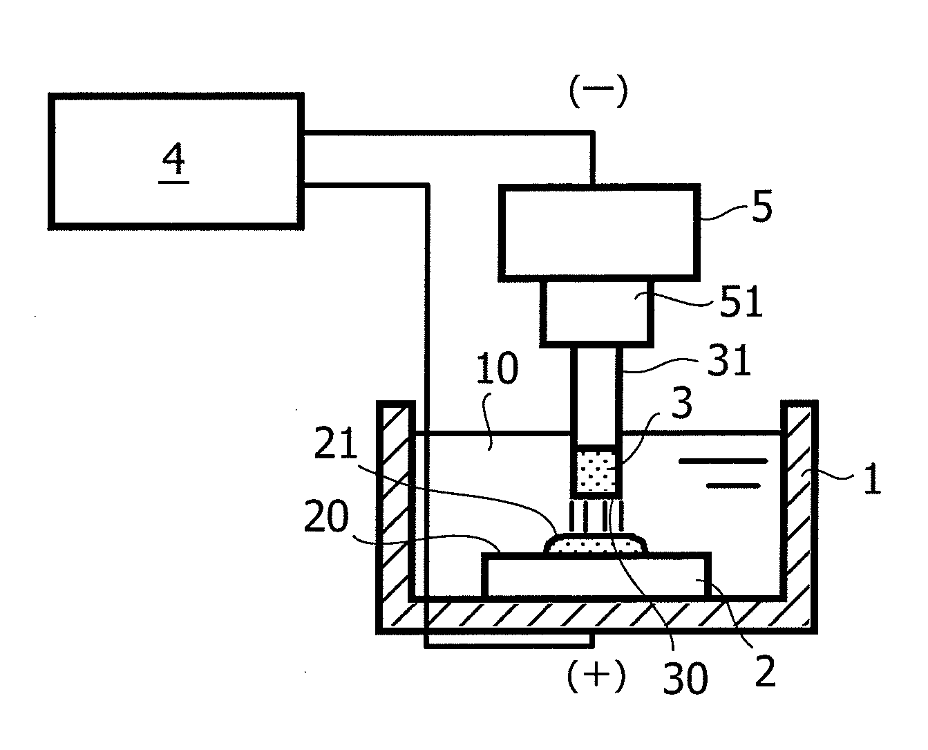
[0017]According to the present invention, a green compact electrode is obtained through compression molding of a metal powder as a main component thereof, the metal powder including, on a surface thereof, an oxide layer having a significant thickness. The use of the green compact electrode allows metal particles to be eluted therefrom at a temperature far lower than the melting point of the metal itself and deposited onto a treatment target surface for coating formation. Accordingly, elution and deposition of the metal component can be performed by pulsed discharge in such a short period of time that no carbide with the metal component may be produced. A coating can therefore be formed without a large amount of heat input into the treatment target surface. Consequently, a highly heat-resistant and wear-resistant coating mainly containing a hard and high melting point metal can be formed even on a low melting point metal such as an aluminum material.
[0018]Moreover, a coating can be formed mainly with a metal component, instead of allowing the coating form to depend on a carbide. Thus, no decrease in conductivity of the coating surface is induced, whereby a thick coating is obtained. Additionally, a uniform coating can be formed without variation of its component in the thickness direction. Also, because the coating form is not dependent on carbide, a working fluid other than an organic working fluid can be used, as long as it is an insulating working fluid which does not react with the metal component. Accordingly, it is also possible to form a coating containing no carbide, irrespective of the electrical discharge conditions.
[0019]In the present invention, the metal powder is preferably a powder of one metal selected from the group consisting of molybdenum (Mo), tungsten (W), chromium (Cr), molybdenum alloys, tungsten alloys, and chromium alloys. Meanwhile, the metal powder may be a mixed powder of two or more metals selected from the group consisting of molybdenum, tungsten, chromium, molybdenum alloys, tungsten alloys, and chromium alloys. Any of these metals from Group 6 of the periodic table and their alloys may be used alone to form a highly heat-resistant and wear-resistant coating.
[0020]Furthermore, the green compact electrode of the present invention is preferably formed through compression molding of the metal powder with a metal soap added thereto. The addition of a metal soap of course improves the moldability of the green compact electrode, but also promotes elution of the metal component at the time of the electrical discharge coating treatment. This is useful when a coating is formed by performing pulsed discharge for a short period of time while suppressing heat input into the treatment target surface.
[0021]Furthermore, the green compact electrode of the present invention is preferably formed through compression molding of the metal powder with a copper powder or a silver powder added thereto. The addition of a copper powder or a silver powder makes uniform the conductivity of the porous green compact electrode and therefore allows uniform pulsed discharge that occurs between the electrode and the treatment target surface. This is useful in preventing defects in the coating due to localized electrical discharge.

Problems solved by technology

Aluminum and its alloys (hereinbelow, simply referred to as an aluminum material) are light in weight and excellent in workability, but have drawbacks of poor wear resistance and corrosion resistance.
Also, to shield an aluminum material, which is poor in high-temperature strength, from high temperatures, coating processes such as plating and thermal spraying have been used industrially.
However, anodization processes and plating have a disadvantage in that since they utilize electrochemical reactions in electrolytic solutions, it is difficult to partially treat an aluminum material.
In addition, thermal spraying has a disadvantage in that since a large amount of heat is input into an aluminum material, the aluminum material is distorted by the heat.
Moreover, vapor deposition processes such as PVD and CVD have a disadvantage of high equipment cost since a treatment furnace needs to be under vacuum.
The electrical discharge coating treatment as above improves the wear resistance due to the high hardness carbide, but has a problem of not being able of yield such a thick coating that the aluminum material can be shielded from high temperatures.
This is attributable to the fact that as a ratio of carbide on the coating surface increases along with the progress of the coating deposition, the conductivity of the coating surface decreases, and thus the pulsed discharge fails to occur properly.
Even if pulsed discharge is caused by applying a higher voltage, the carbide on the coating surface, which has a high melting point and poor in reactivity, hinders transfer of eluted electrode material, making it difficult to achieve thick coating formation.
However, when a low melting point metal such as an aluminum material is used in the above electrical discharge coating treatment using the green compact electrode in which the less-easily-carbonizing metal is mixed, the aluminum material is eluted by the heat of electrical discharge more than the electrode material is eluted.
Hence, the transferring itself of the electrode material and its carbide onto the aluminum material surface is difficult.
Thus, thick coating formation cannot be expected for the aforementioned reason.
This leads to deposition of the carbide in the form of a large mass, and thus a coating including many defects is formed.

Method used


Image

  • Electrical Discharge Coating Method and Green Compact Electrode Used Therein
  • Electrical Discharge Coating Method and Green Compact Electrode Used Therein
  • Electrical Discharge Coating Method and Green Compact Electrode Used Therein

Examples


examples

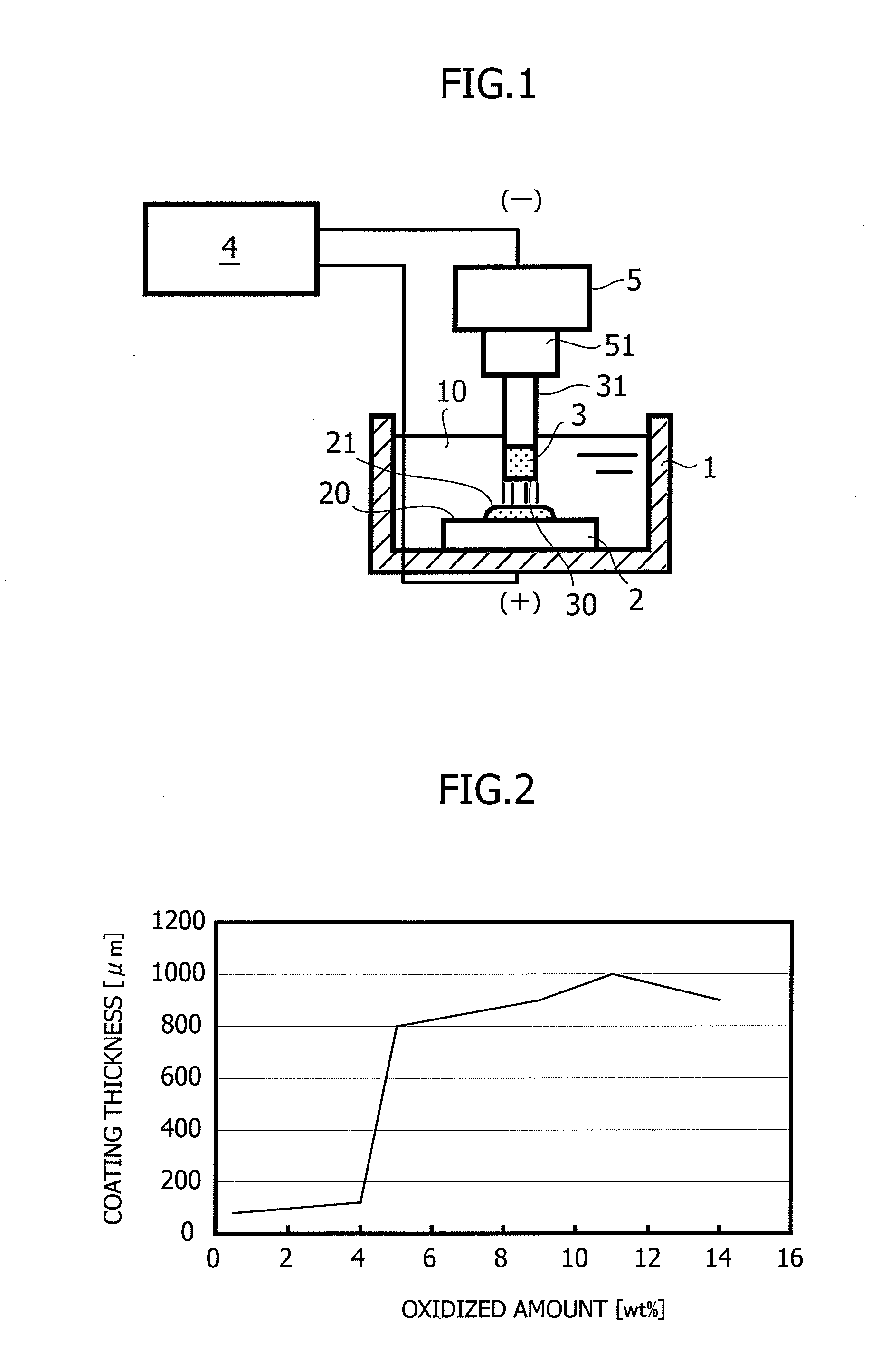
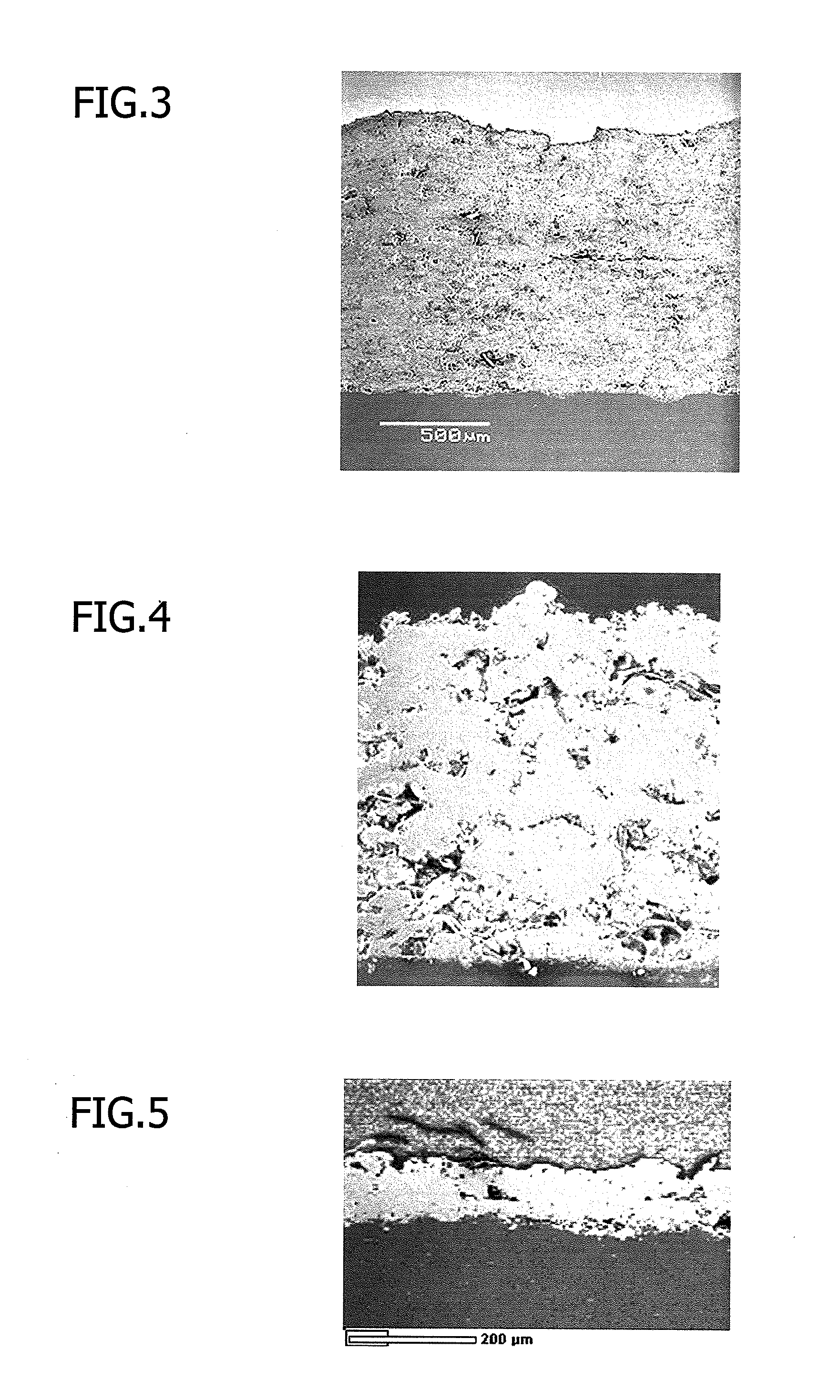
[0065]To test the above-described influence on coating thickness of the oxide layer on the metal powder surface, the following experiments were carried out. Specifically, an electrical discharge coating treatment was performed on surfaces of an aluminum material, a magnesium material, and a titanium material while changing only the amount of oxidation of metal powder but without changing the formation conditions of a green compact electrode and the electrical discharge conditions thereof. Then, changes in coating thickness after the treatment were examined.

[0066]The experiment on the surface of the aluminum material was carried out as follows. A molybdenum powder having an average particle diameter of 2 μm was used as the metal powder. Columnar green compacts each having a diameter of 13.8 mm were prepared at a molding pressure of 400 MPa while changing the oxidized amount of the metal powder in a range from 3 to 14% by weight through an oxidation treatment performed under atmospher...


PUM

PropertyMeasurementUnit
particle diameteraaaaaaaaaa
diameteraaaaaaaaaa
thicknessaaaaaaaaaa

Abstract

An electrical discharge coating method comprising the steps of: generating pulsed discharge between a green compact electrode 3 and a treatment target surface 20 in a working fluid 10; thereby, depositing a component of the green compact electrode 3 onto the treatment target surface 20 so as to form a coating 21, wherein the generating includes using the green compact electrode 3 which is formed through compression molding of metal powder having an oxide layer on each particle surface 20 thereof, as a main component thereof, the oxide layer being thicker than an oxide film normally obtained in air at normal temperature, whereby the metal component of the green compact electrode 3 is deposited onto the treatment target surface 20 so as to form the coating 21 containing the metal component as a main component thereof. It is possible to form a thick coating mainly containing a high hardness metal even on a low melting point metal such as an aluminum material, without depending on a carbide that reduces conductivity.

Description

TECHNICAL FIELD[0001]The present invention relates to an electrical discharge coating method for coating a surface of a treatment target through pulsed discharge on the treatment target using a green compact electrode of a metal powder or the like. In particular, the present invention relates to an electrical discharge coating method allowing coating of a low melting point metal, such as aluminum, with a hard thick coating, and also to a green compact electrode used therein.BACKGROUND ART[0002]Aluminum and its alloys (hereinbelow, simply referred to as an aluminum material) are light in weight and excellent in workability, but have drawbacks of poor wear resistance and corrosion resistance. Thus, anodization processes and vapor deposition processes such as PVD and CVD have been developed as surface treatment methods for coating a surface of an aluminum material with a harder coating. Also, to shield an aluminum material, which is poor in high-temperature strength, from high temperat...

Claims


Application Information

Patent Timeline
Patent Type & Authority Applications(United States)
IPC IPC(8): C25D5/18C25D17/10
CPCB22F2998/00B23K35/00B23K35/002B23K35/0244B23K35/0261C23C26/00C21D1/70B22F1/02C22C32/0031B22F1/16
Inventor KOBAYASHI, MASAHIKO
Owner SUZUKI MOTOR CORP
Learn More