Light-transmitting vibration unit and module thereof

a vibration unit and light-transmitting technology, applied in the field of vibration units, can solve the problems of inability to meet user requirements for purely touch control, inability to produce vibrations for its application in speakers, and inability to use a supersonic transducer as a primary device, etc., to achieve the effect of facilitating operation, enhancing electric signal passing through the vibration unit and increasing voltag

Inactive Publication Date: 2011-02-24
J TOUCH CORPORATION
View PDF7 Cites 42 Cited by
  • Summary
  • Abstract
  • Description
  • Claims
  • Application Information

AI Technical Summary

Benefits of technology

[0032]To facilitate an operation by persons with a visual impairment, the electric signal passing through the vibration unit is enhanced slightly. In other words, the vibration driven component is able to generate a higher voltage. For instance, the voltage intensity used in Chinese medicine and physical therapy is increased in such a way that a slight muscle movement is produced in human dermis or subcutaneous tissue after the electric signal is passed, and such increase of voltage intensity causes no harm to users.
[0033]It is noteworthy to point out that each vibration unit in the vibration...

Problems solved by technology

Although this published patent has disclosed a flexible supersonic transducer, yet the flexible supersonic transducer lacks of light-transmittably, and produces very limited vibrations for its application in a speaker.
So the transducers of this sort cannot be used as a primary device for producing vibrations.
As the development of the touch control technology advances, a purely touch control no longer can meet the user requirements anymore.
When a general user operates a touch display panel, the user is limited by factors including the sensing sensitivity of the touch display panel, the response time of the operating system, and the different personal tactile sensing, and the user usually cannot determine instantly whether or no...

Method used


Image

  • Light-transmitting vibration unit and module thereof
  • Light-transmitting vibration unit and module thereof
  • Light-transmitting vibration unit and module thereof

Examples


Embodiment Construction

[0046]To make it easier for our examiner to clearly understand the technical characteristics of the invention, we use the following preferred embodiments together with the attached drawings for the detailed description of the invention.

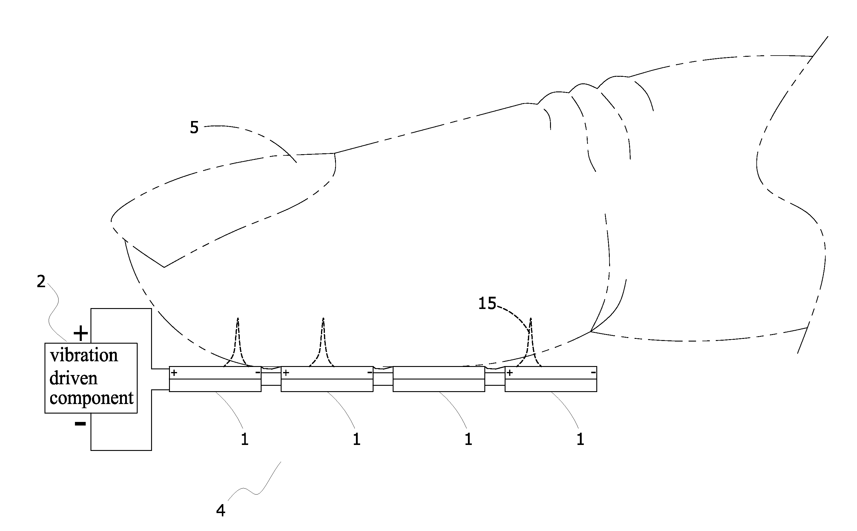
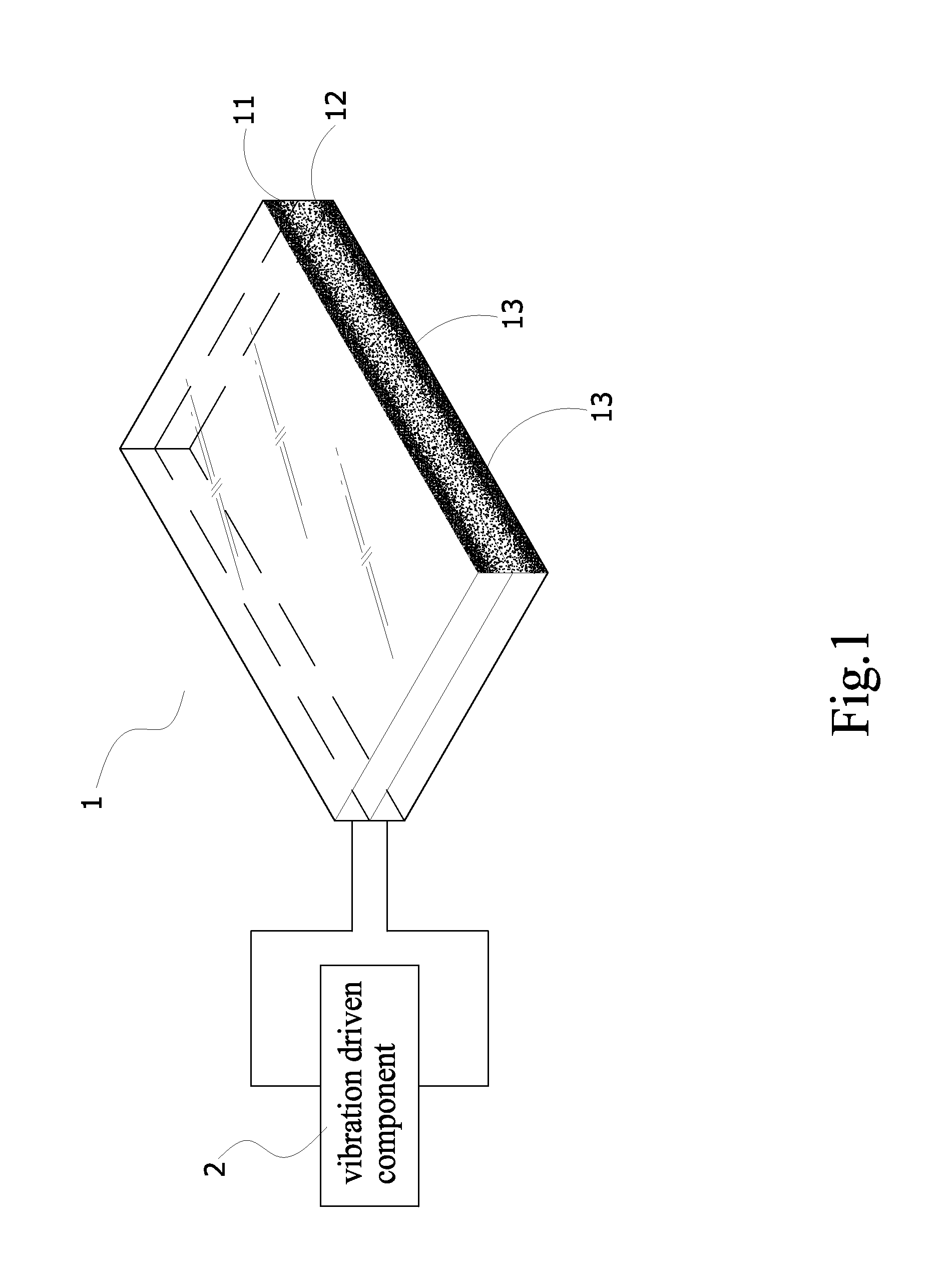
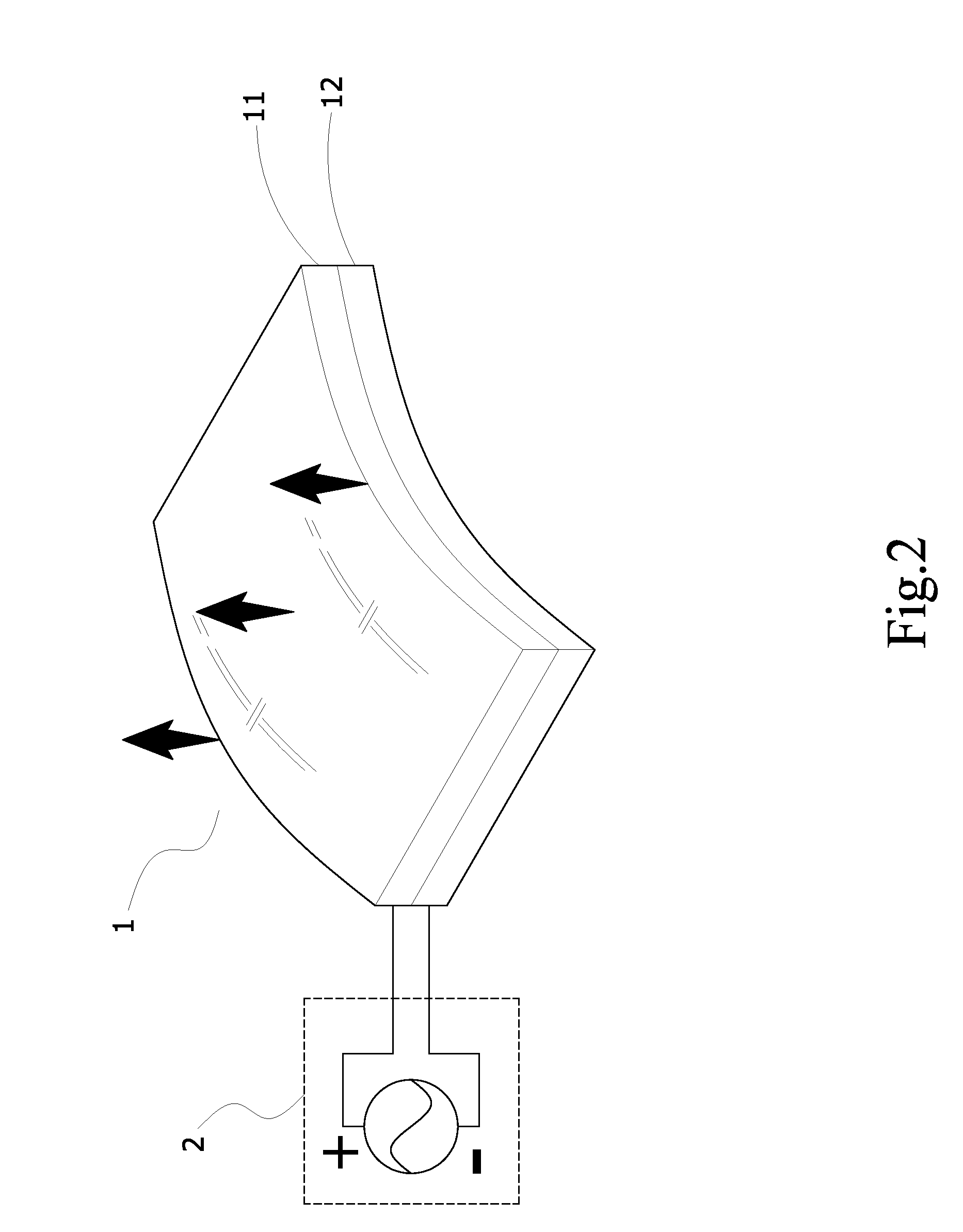
[0047]With reference to FIGS. 1 to 3 for a perspective cross-sectional view and schematic views of movements in accordance with a preferred embodiment of the present invention, the light-transmitting vibration unit includes a vibration unit 1, comprising a first substrate 11, a second substrate 12 and a preinstalled vibration driven component 2.

[0048]The first substrate 11 is made of a light-transmitting plastic material, and doped with a conductive polymer material 13, such that the first substrate 11 has the properties of flexibility, light transmittance and internal uniform resistance.

[0049]The second substrate 12 is stacked onto the bottom of the first substrate 11. Similar to the first substrate 11, the second substrate 12 has the properties of f...


PUM

PropertyMeasurementUnit
Electrical resistanceaaaaaaaaaa
Shapeaaaaaaaaaa
Electrical conductoraaaaaaaaaa

Abstract

In a light-transmitting vibration unit and the module thereof, which the vibration unit comprises a first and a second substrates stacked sequentially with each other, and made of a conductive polymer material, such that both first and second substrates have light transmittance and uniform resistance, and after a vibration driven component is electrically coupled to the first and second substrates, an electric field will be acted for converting electric energy into mechanical energy to produce vibrations. If the vibration unit is coupled directly to a touch-sensitive display unit, an image displayed by the touch-sensitive display unit will be able to pass through the vibration unit, and the vibrations produced by the vibration unit will be more directly transmitted to a touch object.

Description

BACKGROUND OF THE INVENTION[0001]1. Field of the Invention[0002]The present invention relates to a vibration unit, and more particularly to a vibration unit which is light-transmittable and flexible.[0003]2. Description of the Related Art[0004]As piezoelectric materials develops, the size regardless of volume or thickness of actuators including piezoelectric actuators, piezoelectric motors, ultrasonic motors, electrets or related thin actuators made of a piezoelectric material is minimized. Since the principle of piezoelectric effect (which is a prior art technology disclosed years ago, and thus will not be described here) is mainly divided into two types: direct piezoelectric effect and converse piezoelectric effect. If a pressure is applied to a piezoelectric body, then the electric dipole moment of the piezoelectric body will be compressed and shortened together with the material. Now, the resistance against the aforementioned tendency in the piezoelectric body will generate a vo...

Claims


Application Information

Patent Timeline
IPC IPC(8): H01L41/04G06F3/041C08K3/22C08K3/24C08L101/00H01L41/08H01L41/09H01L41/193H01L41/22H01L41/37H01L41/45H02N2/00H03H9/17
CPCF03G7/005Y10S310/80G09B21/003G06F3/016H03H9/17H10N30/857
Inventor YEH, YU-CHOUCHIANG, MIN-HUI
Owner J TOUCH CORPORATION
Why Eureka
Try Eureka