Oxidation-reduction active mass and chemical-looping combustion method

a technology of active mass and oxidation reduction, which is applied in the direction of metal/metal-oxide/metal-hydroxide catalysts, machines/engines, etc., can solve the problems of increasing the cost price of the particles involved in the clc method, affecting the process, and no noble use of the catalyst used

Inactive Publication Date: 2011-03-03
INST FR DU PETROLE +1
View PDF2 Cites 33 Cited by
  • Summary
  • Abstract
  • Description
  • Claims
  • Application Information

AI Technical Summary

Benefits of technology

[0066]Advantageously, a fresh fluidized-bed catalytic cracking catalyst is made up of zeolite and of a matrix. The most commonly used zeolite is the USY zeolite. In some cases, other zeolites are used, such as ZSM-5, often as an additive, in a proportion of 1 to 15% in the inventory of the catalytic cracking unit, so as to confer particular properties on the catalyst and, for example, to maximize the propylene production. The zeolite content of the catalyst generally ranges between 10 and 50 wt. %. Preferably, a catalytic cracking catalyst comprises a USY or ZSM-E zeolite integrated in a silica-alumina matrix of variable composition.
[0071]The metal content of the used FCC catalysts being very low, the direct use of these catalysts in the chemical looping combustion technology would require a high catalyst mass flow rate that is practically unthinkable in the current state of the circulating fluidized bed technology. In order to make these wastes from the refining industry useful for chemical looping combustion, the amount of metal contained in the used catalysts can be increased by impregnation of metal salts. The traces of nickel, iron and vanadium present in the used FCC catalyst contribute to the oxygen transfer capacity of the materials obtained after impregnation / calcination.
[0088]The pressure of the method is adjusted according to the use of the combustion gases. Thus, to carry out total combustion, a low pressure is advantageously used to minimize the gas compression energy cost and thus to maximize the energy yield of the plant. To produce synthesis gas, one will advantageously work under pressure in some cases, in order to avoid compression of the synthesis gas upstream from the downstream synthesis process: the Fischer-Tropsch process operating for example at pressures ranging between 20 and 40 bars, it may be interesting to produce the gas at a higher pressure.

Problems solved by technology

Using a binder allows to provide the mechanical strength required for the particles, but it also increases the cost price of the particles involved in the CLC method.
The presence of metals on the catalyst is detrimental to the process.
However, there is currently no noble use of this used catalyst.
On a world scale, this material however represents very large amounts.
Several hundred thousand tons are annually available on a world scale, at a marginal cost since the used catalyst has no noble use and can therefore be considered as waste.
The used catalysts in catalytic cracking units contain, after use, between 50 and 20,000 ppm metals that decrease their catalytic activity for this process, in particular Ni and V. Such a content is not sufficient to consider using these materials, currently considered to be waste, in an energy production plant by means of the loop redox method on active mass, because the solid circulation rates required for combustion would be too high.

Method used


Image

  • Oxidation-reduction active mass and chemical-looping combustion method
  • Oxidation-reduction active mass and chemical-looping combustion method
  • Oxidation-reduction active mass and chemical-looping combustion method

Examples


example 1

Not Industrially Used FCC Catalyst

[0098]A not industrially used (fresh) FCC catalyst having a BET surface area of 220 m2 / g and an initial pore volume of 0.8 ml / g is dry impregnated with an iron nitrate solution containing 13.9 mass % Fe2O3 equivalent. After calcination in air at 600° C., the impregnated catalyst contains 12 mass % iron oxide. The impregnation / drying / calcination operations are repeated three times, the active mass particles obtained having a Fe2O3 total mass content of 32%.

example 2

Weakly Metal-Laden Industrially Used FCC Catalyst

[0099]A used FCC catalyst from an industrial unit, containing 4000 ppm nickel (Ni) and 2000 ppm vanadium (V), with a BET surface area of 107 m2 / g and an initial pore volume of 0.67 ml / g, is dry impregnated with an iron nitrate solution containing 13.9 mass % Fe2O3 equivalent. After calcination in air at 600° C., the impregnated catalyst contains 11 mass % iron oxide. The impregnation / drying / calcination operations are repeated three times, the active mass particles obtained having a Fe2O3 total mass content of 30%.

example 3

Heavily Metal-Laden Industrially Used FCC Catalyst

[0100]An industrially used FCC catalyst from an industrial unit, containing no nickel but 100 ppm vanadium (V), with a BET surface area of 192 m2 / g and an initial pore volume of 0.64 ml / g, is dry impregnated with an iron nitrate solution containing 13.9 mass % Fe2O3 equivalent. After calcination in air at 600° C., the impregnated catalyst contains 12 mass % iron oxide. The impregnation / drying / calcination operations are repeated three times, the active mass particles obtained having a Fe2O3 total mass content of 33%.

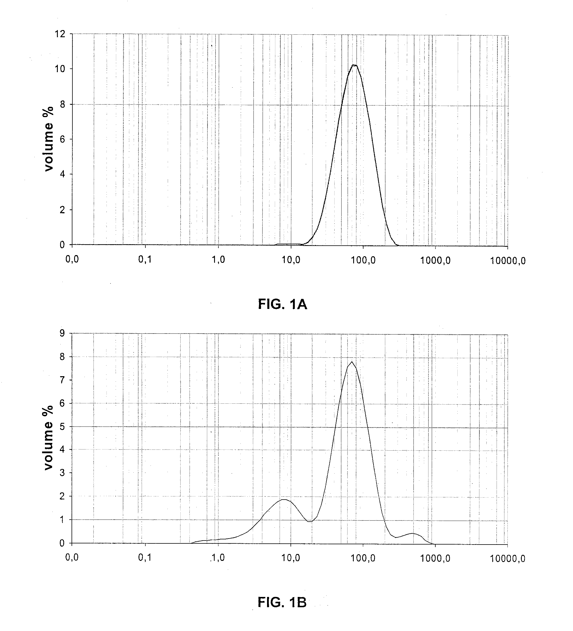
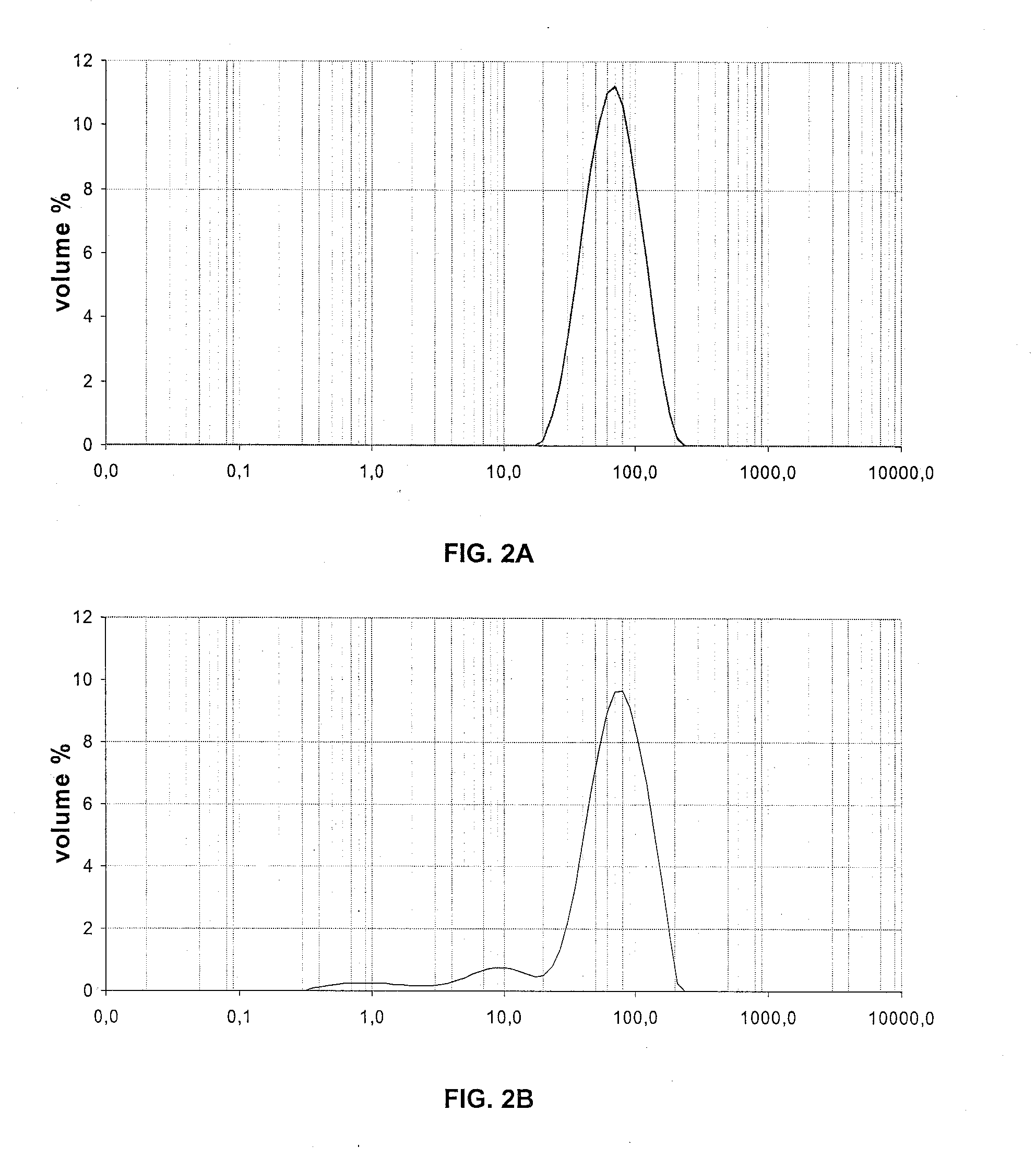
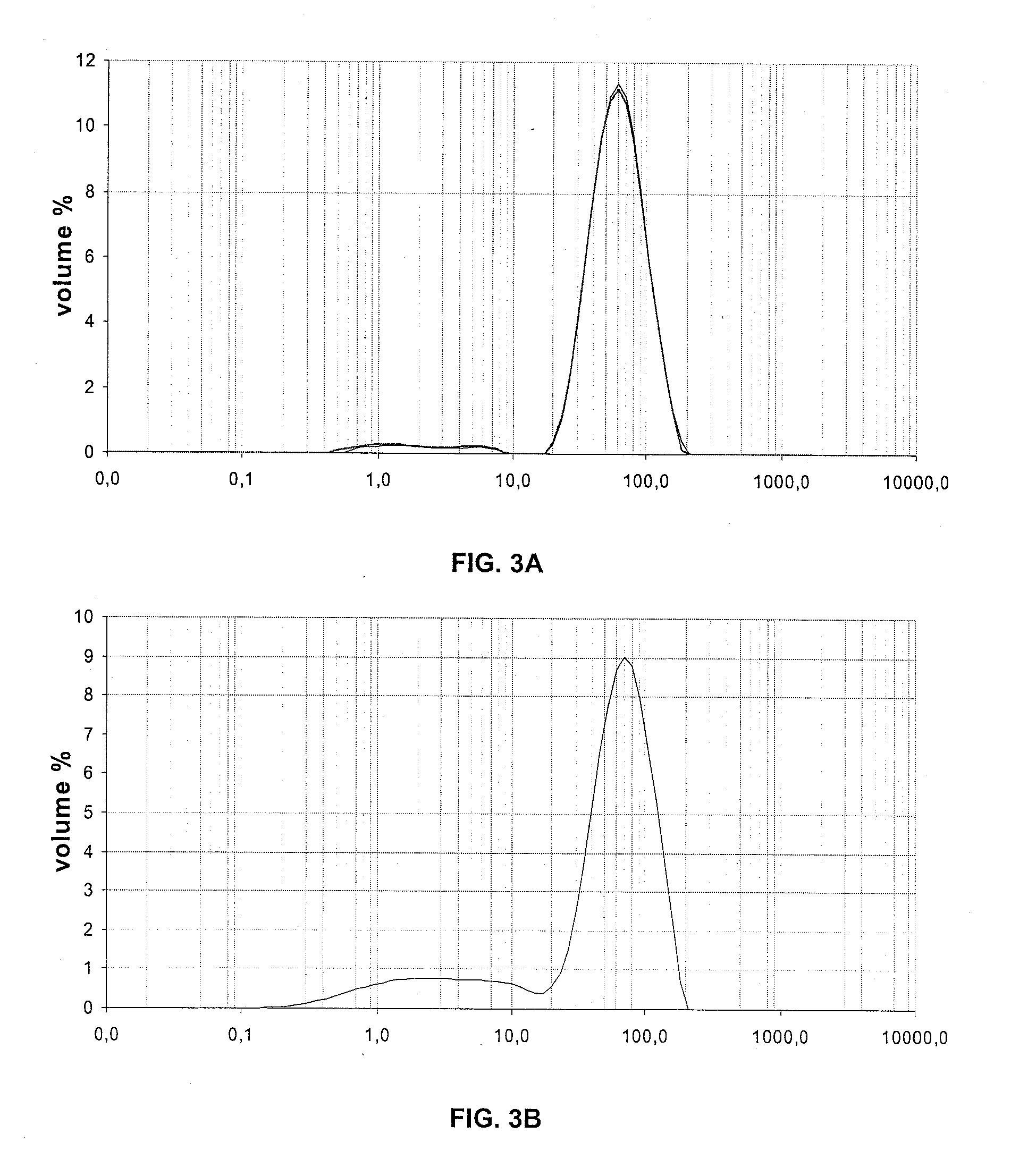
[0101]Size Distribution of the Particles

[0102]The size distribution of the particles has been measured by wet laser grain size analysis, and the results are shown in the table hereunder.

Example 1Example 2Example 3DV10DV50DV90DV10DV50DV90DV10DV50DV90Before impregnation397814938711293261111after impregnation / 7621421973140463126calcination

[0103]FIGS. 1, 2 and 3 respectively show the size distribution of the particles of examp...


PUM

PropertyMeasurementUnit
temperatureaaaaaaaaaa
mean diameteraaaaaaaaaa
diameteraaaaaaaaaa

Abstract

The invention relates to a method for chemical-looping redox combustion on an active mass including a binder, in form of a fluidized-bed catalytic cracking catalyst containing silica and alumina, and a metal oxide active phase. The active mass is obtained by impregnating metal salts on a new or used catalytic cracking catalyst. Advantageously, the invention applies to the sphere of CO2 capture.

Description

FIELD OF THE INVENTION[0001]The invention relates to an active mass and to a fluidized-bed CO2 capture method using this active mass.[0002]We have discovered that a catalyst that has been used in fluidized-bed catalytic cracking plants, generally considered to be valueless industrial waste and usually incorporated in cement or road asphalts, can be used, after impregnation of a metal salt, in a redox loop combustion method allowing notably CO2 sequestration.[0003]The invention consists in using silica and alumina based catalysts shaped to have facilitated flow and transport properties, such as the catalysts used in catalytic cracking processes, in impregnating these catalysts with metal salt solutions, preferably based on iron, nickel, copper, cobalt or manganese, and in using these impregnated catalysts in a combustion process consisting of a zone wherein the fuel is oxidized by the oxygen supplied through reduction of the impregnated catalyst, and of a zone of oxidation of the imp...

Claims


Application Information

Patent Timeline
Patent Type & Authority Applications(United States)
IPC IPC(8): C07C1/04C01B3/30C01B31/20C01B3/38F02C1/00C01B32/50
CPCB01J23/847C10G11/18B01J29/06B01J29/084B01J29/40B01J37/0205B01J2229/16C01B3/344C01B3/386C01B3/40C01B3/44C01B3/48C01B2203/025C01B2203/0283C01B2203/065C01B2203/066C01B2203/08C01B2203/1052C01B2203/1058C01B2203/86C10G1/02C10G11/04B01J23/94Y02P20/584Y02P20/52Y02P30/40Y02P30/00
Inventor LAMBERT, ARNOLDGAUTHIER, THIERRY
Owner INST FR DU PETROLE
Why Eureka
Try Eureka