
Modular quad cell electro-mechanical ozone generation device

a generator device and module technology, applied in the field of modules quad cells, electromechanical ozone generator devices and systems, can solve the problems of not disclosing, suggesting or teaching, prior art reference failing in an area of great need, and not disclosing the use of liquid coolant plates or layer sections, etc., to achieve the effect of reducing power consumption, increasing economic advantages and efficiencies, and saving warm up time and operating costs

Active Publication Date: 2011-03-17
PLASMA TECHNICS
View PDF5 Cites 18 Cited by
  • Summary
  • Abstract
  • Description
  • Claims
  • Application Information

AI Technical Summary

Benefits of technology

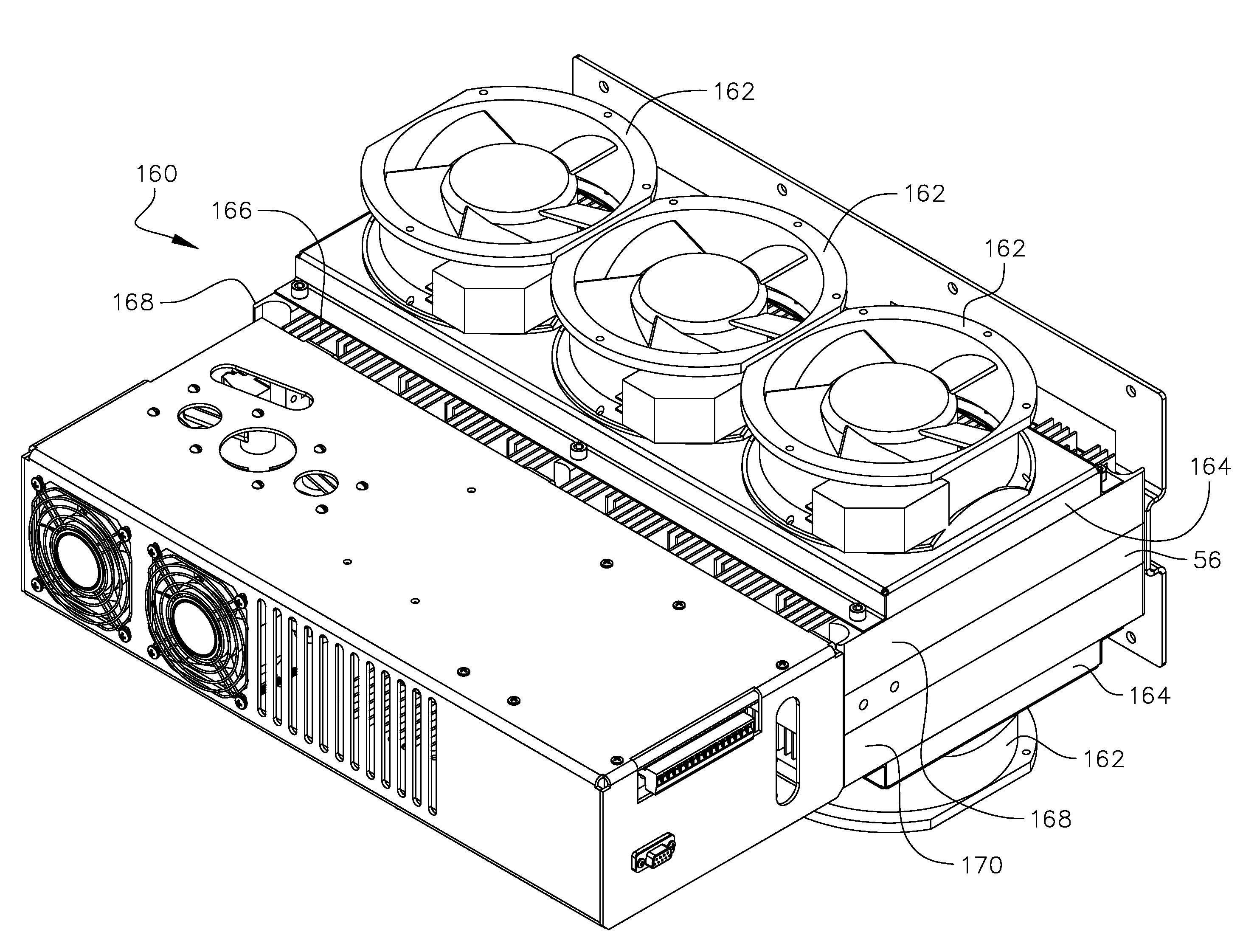
[0018]The upper housing encloses all of the electronics that power and drive the module while the lower housing contains the ozone generating cells, an internal liquid coolant system, a spring plate forced distribution and equalization system, Teflon locators or locators of equally durable material, working in coincidence with the forced distribution and equalization system, an orifice system for maintaining a known and controllable pressure drop across the generation cells, a center body framing element for locating and separating the four ozone generating cells into two pair, as well as liquid coolant inlet and outlet ports, an oxygen inlet port and an ozone outlet port. On either side of the negative electrodes is the internal coolant system formed from a machined plate structure, which forms one of a multitude of section layers making up the lower housing. Each coolant system contains an inlet portion that connects to a liquid manifold (in the preferred embodiment) that is in communication with the inlet port of the center body framing element. The liquid coolant system has a plurality of fins formed therein for moving liquid over the plasma generator (one each on each side of each sub-cell of any one generating cell of the four contained within a module) for removing heat during ozone production therein and for moving excess heat out of the modular ozone generating system. This unique internal cooling system allows the ozone to be cooled as it leaves any given module. Further, the fact that the micro-channel networks for the ozone production is positioned on the opposite side of the ceramic plates helps to keep the system completely dry. This permits the compact size as seen in the present invention, all the while producing a very large capacity output of ozone that could never be accomplished in the prior art as previously discussed in the background of the Invention.
[0019]Each module can slide into a single slot of a tray, wherein each slot has a pair of locating pins and an electrical connection block located at a top portion thereof. The module locating pins and the electrical connection block are formed as one floating piece that permit a slight amount of movement or “play” for module alignment purposes. Aligned in a vertical position along the back side of each slot is a rail connection bar in the tray. There are module inlet and outlet port connectors that also float and permit a slight amount of movement for module alignment purposes within each slot. Further, vertically disposed protuberances can be employed between any of the module inlet and outlet ports to provide horizontal (i.e., side to side) stabilization of the module when inserted into a respective tray slot. Two protuberances are used on the preferred embodiment, however less than or more than two can be employed as needed. All of the floating and locating parts discussed hereinabove work in coincidence to provide stabilization to the module when inserted in the tray and in particular assist in reducing loads at any given connection point or part so that no particular connector bears a greater amount of weight than is necessary or that would cause it to degrade more rapidly. For avoidance doubt, the unique stabilization system of the present invention spreads out the load of the module about all connectors and connection fittings. As an added benefit, this ensures no leakage at any of the ports that pass the liquid, oxygen and ozone in and out of the module and through the tray or other manifold that may be used herein.
[0024]Further, the modular ozone generator of the present invention operates at high frequencies outside the hearing of the human ear (i.e., 25 kHz). This is another vast improvement over the prior, which run at frequencies that are damaging to the human ear (within the range of the human ear, 20-20 k Hz) when in close proximity for long periods of time. Still further, the modular ozone generators of the present invention are all powered equally, one module by itself or in a rack, such that the same pulses are all fired at the same time to avoid a problem in the prior art known as cross-firing.
[0025]Other important aspects of the present invention that should be noted are that each modular unit by themselves, or in a rack, includes self pressure compensation and each modular unit has a fixed orifice to produce back pressure to balance all of the cells to the same output. Further, internal temperature protection shuts down power (power cut-back) to prevent overheating. This is designed into the ozone generating cell control software. Analog controls are provided for safety and on-off functions. Further, algorithms for auto control during start up and shutdown are employed. The system is designed to react to the liquid chemistry and is equipped with an in-house designed oxygen destruct system. Over-voltage protection is designed into the modular units and into any racks housing more than one unit.
[0027]Finally, it should be noted that the modular ozone generator of the present invention or any rack or assembly formed by a plurality of modular units has increased economical advantages and efficiencies that allow the present invention to be labeled as “Green.” These include the instant on-off that saves warm up time and operating costs, the solid state design that reduces power consumption, the power demand that is reduced because of the cooling system that saves a maximum amount of ozone by immediately cooling the ozone upon creation thereof, the power that is conserved by the use of minimal DC pulses for continuing an efficient ozone plasma, the liquid use that is low because it is optimized via computer analysis, the fact that the system maximizes the amount of ozone that gets out of the unit by immediately cooling the ozone, the further fact that the system has instant control for instant reaction to liquid chemistry, which saves on over production of ozone and subsequent destruction, that the system reacts to vary the power in relation to the requirement for ozone, that the system is designed to provide input to the oxygen separator so that it works in unison and reduces compressor loads and therefore subsequent power is reduced, that a minimal foot print reduces building costs as well as up-keep and maintenance costs and finally, but not limited to, that the software is designed to “soft start to last run settings” while instrumentation comes on line and levels out.

Problems solved by technology

However, each modular ozone generator system of this prior art reference employs only a single generator cell with only a single plasma pathway within each module.
This is a disadvantage as locally employed electronics within each individual ozone generating cell would allow greater control and would be a clear improvement over the prior art.
This ozone generator system is considered “water cooled” but it is a “wet cooled system and does not disclose, suggest or teach the use of a liquid coolant system employing a liquid micro-channel network formed on a section layer positioned juxtaposed to the generator cell to affectively cool the ozone being produced.
Therefore, this prior art reference fails in an area of great need.
Further, although Tabata et al. speaks to coolant passages, it fails to disclose the use of a liquid coolant plate or layer section mounted within a center body framing element that is positioned juxtaposed to the ozone generating cells of a modular ozone generation system, of which the liquid coolant plate employs a micro-channel network for passing a liquid coolant there through (i.e., liquid) to significantly reduce the temperature of the ozone being produced there within.
This makes for a difficult device to construct and also a difficult device to repair if any of the flow tube insulation breaks down and needs to be replaced.
The placement of a liquid coolant passage through the high voltage electrode is of poor design and clearly needs improvement thereupon.
However, what is not contemplated, let alone disclosed, taught or suggested, is what to do with the excess heat generated by such a device.
A major factor in designing and implementing large capacity, small configuration ozone generating device, is the issue of heart dissipation.
What can therefore be gathered is that the device does not produce a significant amount of heat and therefore its statement to being large capacity is disingenuous at best.
However, it can not produce the large capacity output, which it purportedly produces unless it employs an integral cooling system, which it clearly does not.
So, although it moves the prior art forward in designing a compact ozone generation unit, it can not be said to be a “large capacity” unit because it fails to properly provide for heat dissipation through some form of a cooling system and therefore falls way short of improving the art of large capacity, small configuration ozone generation units.
For example, nowhere in the prior art has any ozone generator been able to produce a modular unit having four generating cells within one small modular unit, the same which could then be used in a tray that forms a rack.
Still further, nowhere in the prior art has any modular unit been programmed to be completely self-diagnostic and having an instant on feature such that ozone can be produced at the very moment of start up.
Each of the prior art devices known require a start up wait period, which translates into a significant loss of time in ozone production (and therefore a loss of efficiency) when considering large commercial and industrial applications and which is totally unacceptable for military uses.

Method used


Image

  • Modular quad cell electro-mechanical ozone generation device
  • Modular quad cell electro-mechanical ozone generation device
  • Modular quad cell electro-mechanical ozone generation device

Examples


Embodiment Construction

, contained herein below, may be better understood when accompanied by a brief description of the drawings, wherein:

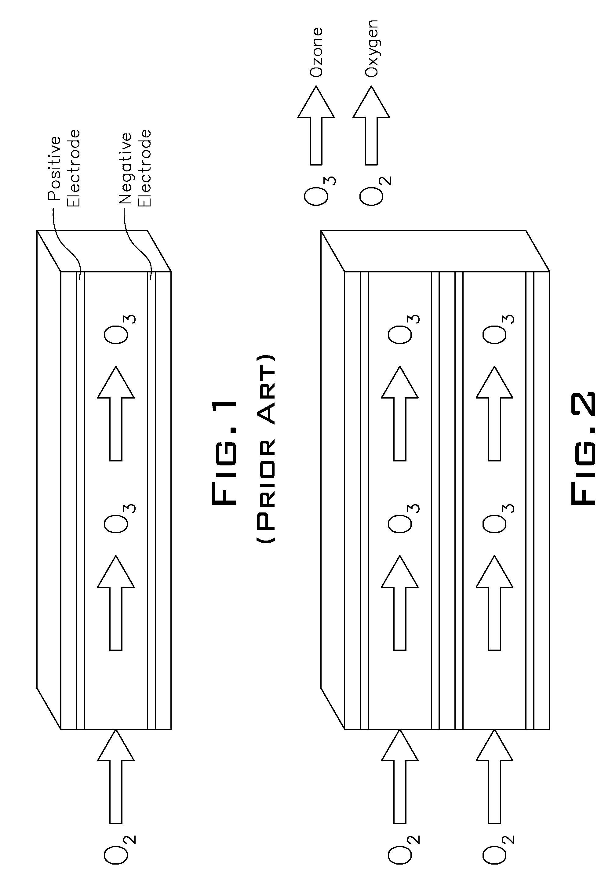
[0029]FIG. 1 is an illustration of a prior art ozone generator that shows how a single pathway of plasma is generated and are moved through the ozone generator between two electrodes;

[0030]FIG. 2 is an illustration of an ozone generator cell employed in the present invention that shows how two pathways of plasma are generated and are moved through the ozone generator cell between separated pairs of electrodes;

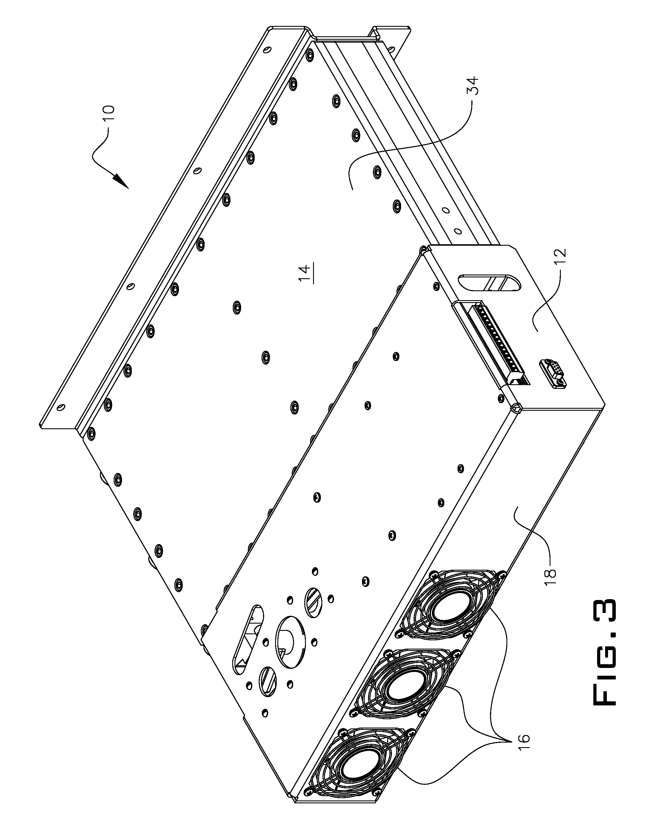
[0031]FIG. 3 is a perspective view of a modular quad cell, liquid cooled electro-mechanical ozone generator system of the present invention having an upper and lower housing and viewed from the top to bottom;

[0032]FIG. 4 is a perspective view the modular ozone generator system of the present invention, viewed from the bottom to the top;

[0033]FIG. 5 is a perspective view of the modular ozone generator system of the present invention with a top cover of the lower ho...


PUM


Abstract

An ozone generation system includes a plurality of modular ozone generating devices, each having an upper and lower housing. The upper housing encloses electrical components for providing high energy power to ozone generator cells of each device to produce an ozone generation output. The lower housing is formed by a multiplicity of section layers enclosing the ozone generator cells and an internal liquid coolant system. Each ozone generator cell has two plasma generation pathways. An orifice is formed in on each one ozone generator cell for maintaining a known and controllable pressure drop across each ozone generator cell. A plurality of ports formed in a center body framing element of the lower housing provides porting for the water in and out, oxygen in and ozone out. The modular devices can be combined on racks having a common manifold system for forming a rack of ozone producing devices for outputting a high yield of ozone.

Description

PRIOR APPLICATIONS[0001]This U.S. non-provisional patent application is a continuation-in-part of U.S. provisional patent application No. 61 / 243,157, filed Sep. 17, 2009.BACKGROUND OF THE INVENTION[0002]1. Field of Invention[0003]This invention relates to a modular quad cell, electro-mechanical ozone generator device and system. More particularly, it relates to a highly-concentrated output modular ozone generator system having four generator cells in each modular ozone generator, which can be combined onto trays forming a rack of ozone generators for providing a high concentration, high output yield of liquid or air-cooled ozone for a multitude of industrial, commercial and military purposes.[0004]2. Description of the Prior Art[0005]Modular ozone generator systems that can be combined to form blocks of generators are known in the prior art. For example, U.S. Pat. No. 6,599,486 to Borgstrom discloses an ozone generator system in which a multitude of plate-type ozone generators are a...

Claims


Application Information

Patent Timeline
Patent Type & Authority Applications(United States)
IPC IPC(8): B01J19/08
CPCC01B13/10
Inventor FRANCIS, JR., RALPH M.MASTOPIETRO, JOHN C.MASTOPIETRO, ANTHONY J.
Owner PLASMA TECHNICS
Learn More