
Exhaust processing and heat recovery system

a technology of exhaust gas and heat recovery system, which is applied in the direction of metal processing, indirect carbon-dioxide mitigation, machines/engines, etc., can solve the problems of increased pressure drop through the air preheater plus lower heat transfer effectiveness, excessive condensation, and fly ash sticking more tightly to the surface, so as to reduce the volume of flue gas and reduce the temperature of the flue gas. , the effect of compactness

Inactive Publication Date: 2011-03-31
ALSTOM ENERGY TECH AG
View PDF10 Cites 22 Cited by
  • Summary
  • Abstract
  • Description
  • Claims
  • Application Information

AI Technical Summary

Benefits of technology

"The present invention relates to a method and system for reducing fouling and increasing the thermal efficiency of an air preheater used in a furnace. The method involves injecting alkaline particles into the flue gas stream to neutralize acidic materials and reduce the accumulation of flue gas particulates on the heat exchange surfaces of the air preheater. The size distribution of the alkaline particles is calculated based on the mass flow rate of the flue gas and the degree of fouling is measured by measuring the pressure drop across the air preheater. The mass flow rate of the alkaline particles is adjusted based on the degree of fouling to reduce the accumulation of flue gas particles on the heat exchange surfaces and increase the thermal efficiency of the air preheater. The system includes an air preheater coupled to the furnace, flue gas sensors, pressure drop sensors, and an alkaline injection system responsive to control signals. The invention allows for more efficient heat recovery from the furnace and reduces the need for excessive fouling or corrosion activities within the air preheater."

Problems solved by technology

However, the lower flue gas temperature range may result in excessive condensation of sulfur trioxide (SO3) or sulfuric acid vapor (H2SO4) that may be present in the flue gas.
This acid causes fly ash to stick more tightly to surfaces.
This “fouling” process impedes the air and flue gas flow thru the air preheater, resulting in increased pressure drop through the air preheater plus lower heat transfer effectiveness.
However, in existing coal and / or oil fired steam generation systems, it is costly to remove additional heat from the exhaust gas stream.
Excessive reduction of the flue gas temperature without consideration for the additional condensation of H2SO4 vapors in the flue gas, will result in excessive fouling of the heat transfer surfaces in the air preheater.

Method used


Image

  • Exhaust processing and heat recovery system
  • Exhaust processing and heat recovery system
  • Exhaust processing and heat recovery system

Examples


Embodiment Construction

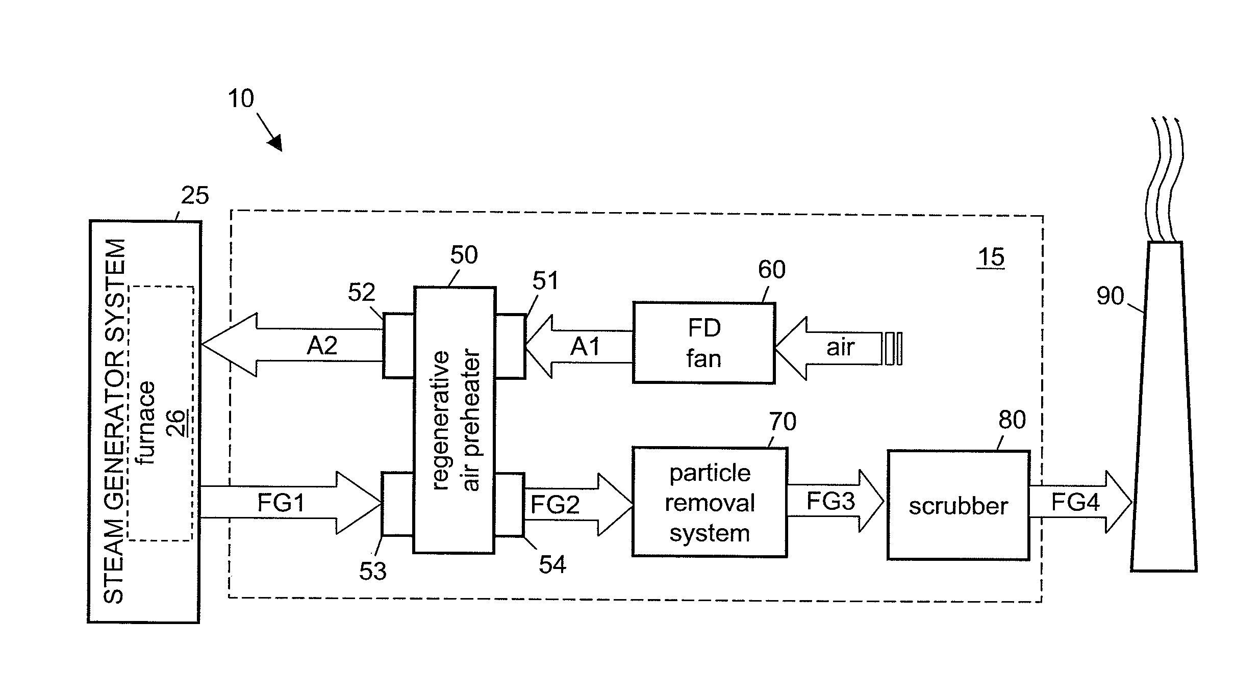
[0058]The purpose of this invention is to provide a means to extract more heat from the flue gas as it passes through the gas side of the regenerative air heater without the heat transfer surfaces of the equipment downstream of the regenerative air preheater becoming excessively fouled or corroded.

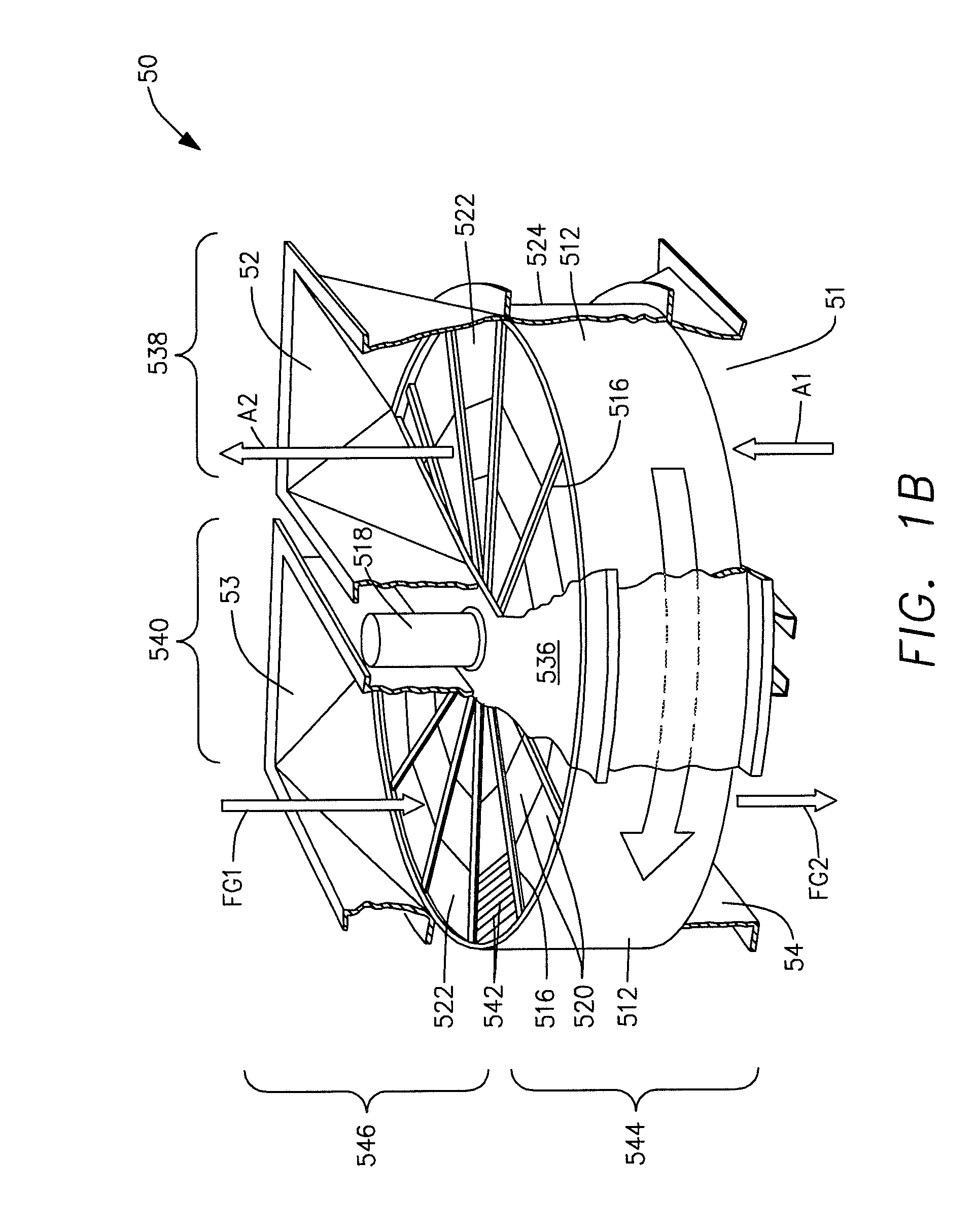
[0059]The present invention is directed to control the amount of acid that is condensed and accumulated on heat transfer elements of an air preheater and to thereby improve the effectiveness of the air preheater in extracting heat from a flue gas stream FG1 from the combustion chamber of, for example, a furnace. A further aspect of the invention is directed to controlling the “wetness” of the deposit on the heat transfer surfaces so that the deposit can be maintained in a condition that allows it (the deposit) to be easily removed while the air preheater is in operation. A further aspect of the proposed invention is directed to an air preheater that is configured to allow for the distribut...


PUM

PropertyMeasurementUnit
diameteraaaaaaaaaa
diameteraaaaaaaaaa
sizeaaaaaaaaaa

Abstract

A thermally efficiency regenerative air preheater 250 extracts more thermal energy from the flue gas exiting a solid fuel fired furnace 26 by employing an alkaline injection system 276. This mitigates acid fouling by selectively injecting different sized alkaline particles 275 into the air preheater 250. Small particles provide nucleation sites for condensation and neutralization of acid vapors. Large particles are injected to contact and selectively adhere to the heat exchange elements 542 and neutralize liquid acid that condenses there. When the deposit accumulation exceeds a threshold, the apparatus generates and utilizes a higher relative percentage of large particles. Similarly, a larger relative percentage of small particles are used in other cases. Mitigation of the fouling conditions permits the redesign of the air preheater 250 to achieve the transfer of more heat from the flue resulting in a lower flue gas outlet temperature without excessive fouling.

Description

CROSS REFERENCE TO RELATED APPLICATIONS[0001]This application claims priority from U.S. Application Ser. No. 61 / 245,822 “Exhaust Process and Heat Recovery System” by James W. Birmingham and Kevin J. O'Boyle filed Sep. 25, 2009 and incorporates the material of the priority application to the extent that it does not contradict the present application.BACKGROUND[0002]1. Field of the Invention[0003]This invention relates generally to an exhaust processing and heat recovery (EPHR) system and method for use with fossil fuel fired furnaces. More particularly, the present invention relates to an EPHR system in which alkaline particles are introduced into a flue gas stream to allow additional heat extraction and reduce fouling of air preheater equipment.[0004]2. Discussion of Related Prior Art[0005]Many power generation systems are powered by steam that is generated via furnaces fired by fossil fuels, such as, for example, coal or oil. A typical power generation system is generally depicted ...

Claims


Application Information

Patent Timeline
Patent Type & Authority Applications(United States)
IPC IPC(8): F23J15/00F23L15/02F28F19/00
CPCC21B9/14C21B2100/06C21C5/38C21C2100/06F23J15/006F27D17/008F23J2217/102F23J2219/40F23L15/02F27D17/004F23J15/02Y02P10/122Y02E20/34Y02P10/32F01K23/06F22B1/18
Inventor BIRMINGHAM, JAMES W.O'BOYLE, KEVIN J.
Owner ALSTOM ENERGY TECH AG
Learn More