High efficiency low energy microwave ion/electron source

a low energy, microwave technology, applied in plasma technology, vacuum evaporation coating, ion beam tubes, etc., can solve the problems of low deposition rate, adversely affecting deposition, and difficult escape of deposition atoms without being ionized by energetic electrons, etc., to achieve high density plasma

Inactive Publication Date: 2011-03-31
APPLIED MATERIALS INC
View PDF79 Cites 20 Cited by
  • Summary
  • Abstract
  • Description
  • Claims
  • Application Information

AI Technical Summary

Benefits of technology

[0014]Embodiments of the invention utilize a coaxial microwave ion source with a containment shield and an extraction grid to provide a high density plasma from which ions of relatively low energies. The extraction grids may be biase

Problems solved by technology

The ionization of atoms requires a high density plasma, which makes it difficult for the deposition atoms to escape without being ionized by energetic electrons.
Capacitively generated plasmas are usually lightly ionized, resulting in low deposition rate.
A drawback with this technique is that ions with about 100 eV in energy bombard the coil, erode the coils, and then generate sputtered contaminants that may adversely affect the deposition.
And the high energy of the ions may damage the substrate.
But this technique does not provide a

Method used


Image

  • High efficiency low energy microwave ion/electron source
  • High efficiency low energy microwave ion/electron source
  • High efficiency low energy microwave ion/electron source

Examples


Embodiment Construction

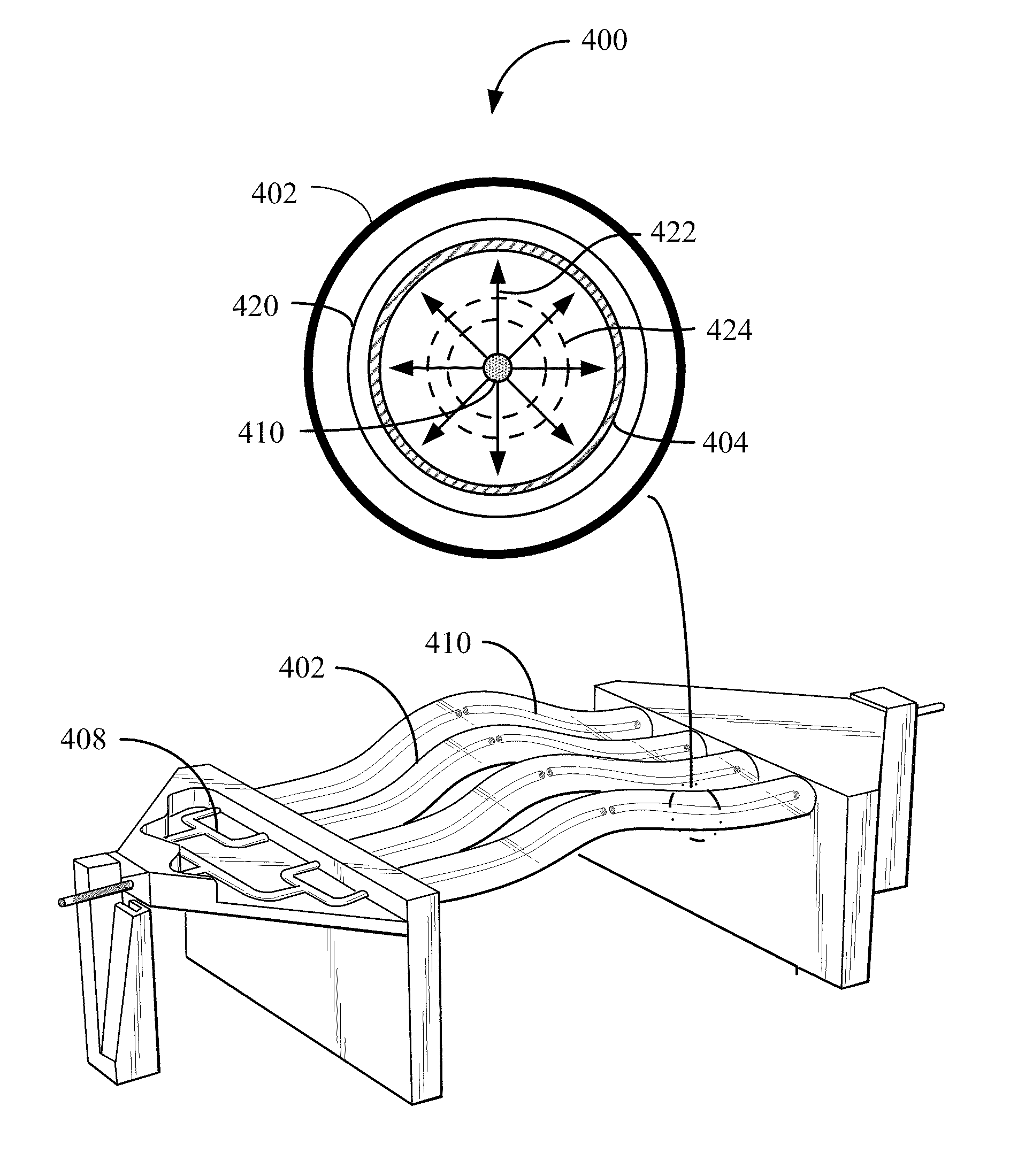
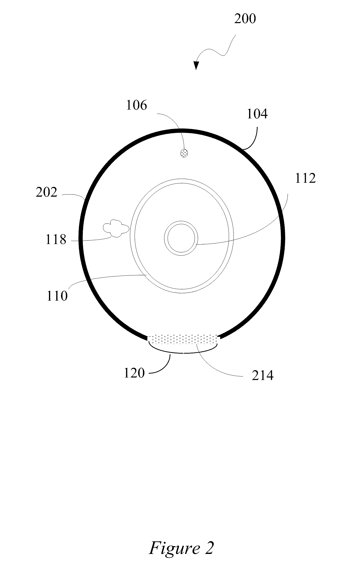
[0024]Embodiments of the invention provide device and methods for depositing low energy plasma species using a microwave plasma source. In some embodiments, a plasma with low plasma species energy can be formed using a coaxial microwave source. And an extraction grid can be used to provide the proper energy to the plasma species in order to deposit the plasma species on a substrate.

[0025]Microwave Plasma

[0026]In comparison with typical radio frequency (RF) coupled plasma sources microwave plasma sources can be used to achieve higher plasma densities (e.g., ˜1012 ions / cm3) and higher deposition rates. These improvements can be a result of improved power coupling and absorption at 2.45 GHz when compared to a typical radio frequency (RF) coupled plasma source at 13.56 MHz. One drawback of using RF plasma is that a large portion of the input power is dropped across the plasma sheath (dark space). By using microwave plasma, a narrow plasma sheath can be formed and more power can be absor...


PUM

PropertyMeasurementUnit
Dielectric polarization enthalpyaaaaaaaaaa
Electrical conductivityaaaaaaaaaa
Dimensional stabilityaaaaaaaaaa

Abstract

A microwave charged particle source is provided according to various embodiments of the invention. The microwave charged particle source can include a coaxial antenna for generating microwaves and a dielectric layer surrounding the antenna. The microwave charged particle source can also include a first gas line outside the dielectric layer for providing sputtering gases and/or a second gas line for providing cooling gas in a space between the antenna and dielectric layer. The microwave charged particle source can further include a containment shield partially surrounding the dielectric layer and an extraction grid disposed on or near an aperture in the containment shield. In use, charged particles can be formed with the generated microwaves from sputtering gases. And the charged particles can be accelerated under an electric field created from a voltage applied to the extraction grid. A method for providing microwave charged particle source is also provided.

Description

CROSS-REFERENCES TO RELATED APPLICATIONS[0001]This patent application is a non-provisional of and claims the benefit of U.S. Provisional Patent Application No. 61 / 224,224, entitled “High Efficiency Low Energy Microwave Ion / Electron Source,” filed Jul. 9, 2009, the entire disclosures of which are incorporated herein by reference for all purposes.[0002]This patent application is a non-provisional of and claims the benefit of U.S. Provisional Patent Application No. 61 / 224,234, entitled “Curved Surface Wave Fired Plasma Line for Coating of 3 Dimensional Substrates,” filed Jul. 9, 2009, the entire disclosures of which are incorporated herein by reference for all purposes.[0003]This patent application is a non-provisional of and claims the benefit of U.S. Provisional Patent Application No. 61 / 224,371, entitled “Simultaneous Vertical Deposition of Plasma Displays Layers,” filed Jul. 9, 2009, the entire disclosures of which are incorporated herein by reference for all purposes.[0004]This pa...

Claims


Application Information

Patent Timeline
IPC IPC(8): H05H1/24
CPCC23C14/221H01J27/16H05H1/46H01J37/3222H01J37/32192
Inventor STOWELL, MICHAEL W.
Owner APPLIED MATERIALS INC
Why Eureka
Try Eureka