Semiconductor device and manufacturing method thereof
a semiconductor device and manufacturing method technology, applied in the field of semiconductor devices, can solve the problems of increasing the power consumption of the semiconductor device, shortening the traveling distance of the in-vehicle electronic device, and limited use time, so as to reduce the concentration of hydrogen, reduce the leakage current, and reduce the effect of power consumption
- Summary
- Abstract
- Description
- Claims
- Application Information
AI Technical Summary
Benefits of technology
Problems solved by technology
Method used
Image
Examples
embodiment 1
[0050]This embodiment describes an example of a cross-sectional structure of a semiconductor integrated circuit.
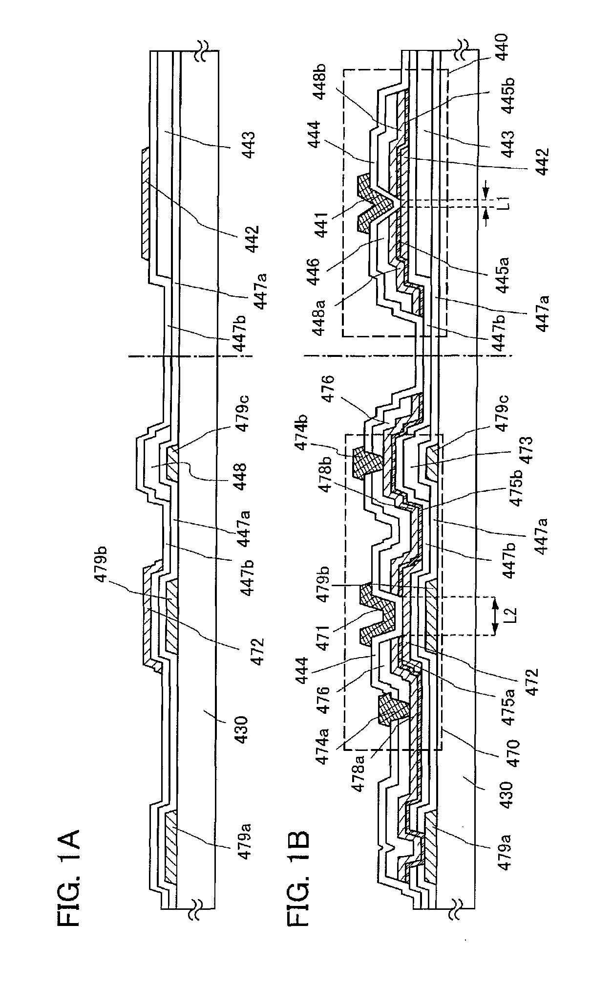
[0051]In this embodiment, one embodiment of a semiconductor integrated circuit and a manufacturing method thereof is described with reference to FIGS. 1A and 1B, FIG. 2, FIG. 3, and FIGS. 4A and 4B.
[0052]An example of a cross-sectional structure of the semiconductor integrated circuit is illustrated in FIGS. 1A and 1B. A thin film transistor 440 illustrated in FIG. 1B is one of top-gate thin film transistors.
[0053]The thin film transistor 440 includes a first insulating layer 447a, a second insulating layer 443, a third insulating layer 447b, an oxide semiconductor layer 442, a first source electrode layer 445a, a second source electrode layer 448a, a first drain electrode layer 445b, a second drain electrode layer 448b, a gate insulating layer 444, and a gate electrode layer 441, over a substrate 430 having an insulating surface.
[0054]Part of the oxide semiconductor layer...
embodiment 2
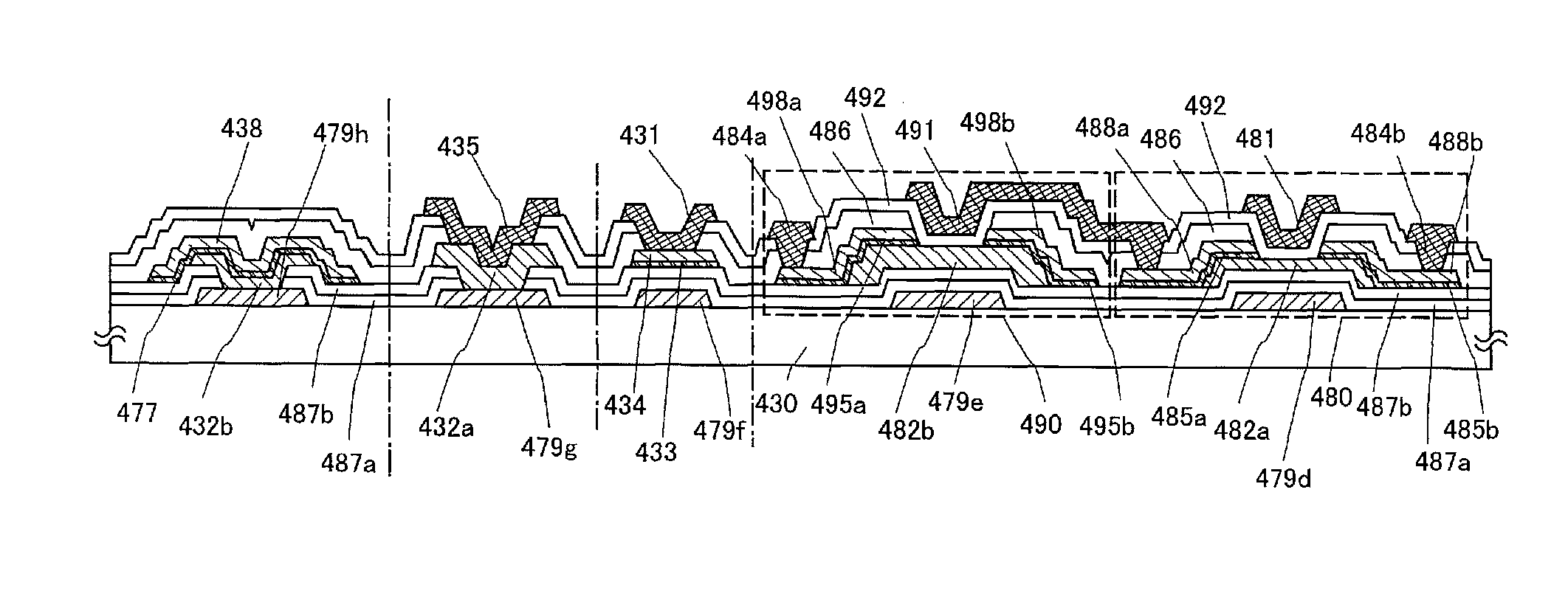
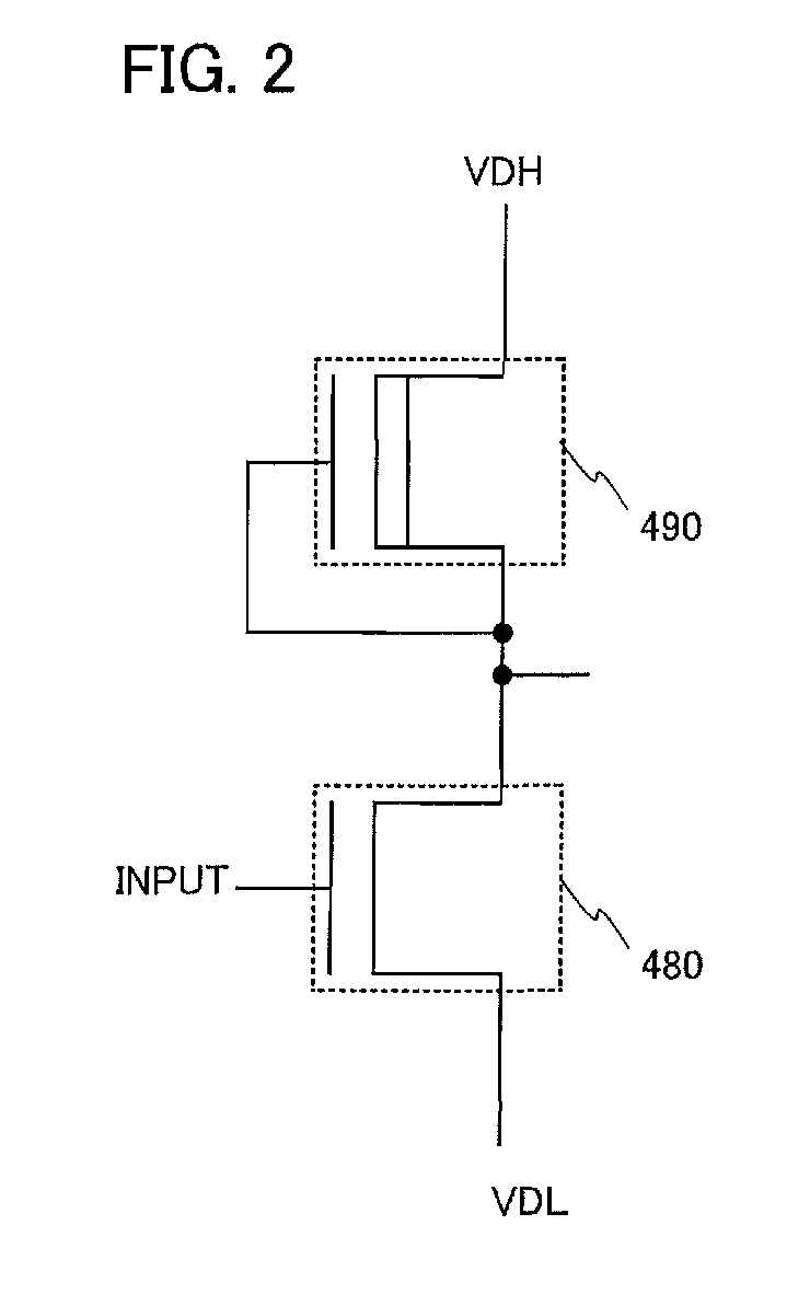
[0131]In Embodiment 1, the thin film transistor 470 including a wiring intersection and the thin film transistor 440 including the gate electrode layer 441 only above the oxide semiconductor layer 442 is described. Hereinafter, an example of forming an inverter circuit of an integrated circuit using two n-channel thin film transistors will be described. Note that since the manufacturing process of the thin film transistor is almost the same as that in Embodiment 1, only different points are described in detail.
[0132]An integrated circuit is formed using an inverter circuit, a capacitor, a resistor, and the like; therefore, a process of forming a capacitor and two kinds of resistors over one substrate in addition to the inverter circuit is also described.
[0133]When the inverter circuit is formed using two n-channel TFTs in combination, there are two kinds of inverter circuits: an inverter circuit having a combination of an enhancement type transistor and a depletion type transistor (...
embodiment 3
[0156]In this embodiment, an example of manufacturing a CPU (central processing unit) using the EDMOS circuit described in Embodiment 2 will be described.
[0157]An example of a block diagram of a CPU is illustrated in FIG. 5. A CPU 1001 illustrated in FIG. 5 includes a timing control circuit 1002, an instruction decoder 1003, a register array 1004, an address logic and buffer circuit 1005, a data bus interface 1006, an ALU 1007, an instruction register 1008, and the like.
[0158]These circuits are manufactured using the thin film transistor, the inverter circuit, the resistor, the capacitor, and the like described in Embodiment 1 or Embodiment 2. The thin film transistors described in Embodiment 1 or Embodiment 2 each use an oxide semiconductor layer with sufficiently reduced hydrogen concentration, whereby the off-current of the thin film transistor can be extremely small. By using a thin film transistor including an oxide semiconductor layer with sufficiently reduced hydrogen concent...
PUM
 Abstract
Description
Claims
Application Information
 - R&D
- Intellectual Property
- Life Sciences
- Materials
- Tech Scout
- Unparalleled Data Quality
- Higher Quality Content
- 60% Fewer Hallucinations
Browse by: Latest US Patents, China's latest patents, Technical Efficacy Thesaurus, Application Domain, Technology Topic, Popular Technical Reports.
© 2025 PatSnap. All rights reserved.Legal|Privacy policy|Modern Slavery Act Transparency Statement|Sitemap|About US| Contact US: help@patsnap.com


