Image processing method, and image processing apparatus

a technology of image processing and image processing apparatus, applied in the direction of duplicating/marking methods, printing, etc., can solve the problems of high pressure, deformation of thermoplastic recording medium, and deformation of flexible recording medium, so as to ensure the effect of repeatability

Inactive Publication Date: 2011-04-21
RICOH KK
View PDF10 Cites 21 Cited by
  • Summary
  • Abstract
  • Description
  • Claims
  • Application Information

AI Technical Summary

Benefits of technology

[0038]The present invention can solve the above-mentioned problems, achieve the object and provide an image processing method and image p

Problems solved by technology

However, when an RF-ID tag as disclosed in Japanese Patent Application Laid-Open (JP-A) No. 2004-265247 and Japanese Patent (JP-B) No. 3998193 is embedded in a thermoreversible recording medium, the thermoreversible recording medium needs to be thickened and the flexibility thereof degrades, and thus high pressure is required for uniformly pressing a heat source against the thermoreversible recording medium.
In addition, in the contact image processing method, a surface of the thermoreversible recording medium is scraped due to repetitive printing and erasure and irregularities are formed therein, and some parts are not in contact with a heating source (e.g., thermal head, and hot stamp).
Thus, the thermoreversible recording medium may not be uniformly heated, causing degradation in image density and erasing failure (see Japanese Patent (JP-B) No. 3161199 and Japanese Patent Application Laid-Open (JP-A) No. 09-30118).
However, in such a laser recording method, when an information-read code such as a two-dimensional code (e.g., character, bar code, and QR code) is recorded, but if an image having a predetermined line width is not precisely formed, the code may not be satisfactorily read through a machine, although the recorded image appears cleanly written visually.
Also, when lines are written on a recording medium in an overlapped manner in an attempt to write a line

Method used


Image

  • Image processing method, and image processing apparatus
  • Image processing method, and image processing apparatus
  • Image processing method, and image processing apparatus

Examples


examples

[0289]Hereinafter, the present invention will be described in more detail with reference to Examples, which however shall not be construed as limiting the scope of the present invention.

[0290]A thermally reversible recording medium capable of reversibly changing in color tone depending on a change in temperature was produced in the following manner.

—Support—

[0291]As a support, a white turbid polyester film of 125 μm in thickness (TETRON FILM U2L98W, produced by TEIJIN DUPONT FILMS JAPAN LTD.) was used.

—Formation First Oxygen Barrier Layer—

[0292]A urethane-based adhesive (produced by Toyo-Morton Ltd., TM-567) (5 parts by mass), isocyanate (produced by Toyo-Morton Ltd., CAT-RT-37) (0.5 parts by mass), and ethyl acetate (5 parts by mass) were mixed and substantially stirred to prepare an oxygen barrier layer coating liquid.

[0293]Next, the oxygen barrier layer coating liquid was applied onto a silica-deposited PET film (produced by Mitsubishi Plastics Inc., TECHBARRIER HX, oxygen permea...

production example 2

Production of Thermoreversible Recording Medium

[0304]A thermoreversible recording medium of Production Example 2 was produced in the same manner as in Production Example 1, except that a first thermoreversible recording layer, a photothermal conversion layer and a second thermoreversible recording layer were produced according to the following procedures.

—Formation of Thermoreversible Recording Layer Containing Photothermal Conversion Material—

[0305]A reversible developer represented by the above Structural Formula (1) (5 parts by mass), a color-erasing accelerator represented by the above Structural Formula (2) (0.5 parts by mass), a color-erasing accelerator represented by the above Structural Formula (3) (0.5 parts by mass), a 50% by mass acrylpolyol solution (hydroxyl group value: 200 mgKOH / g) (8 parts by mass) and methylethylketone (80 parts by mass) were pulverized and dispersed in a ball mill until the average particle diameter became about 1 μm.

[0306]Next, in a dispersion li...

example 1

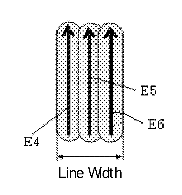
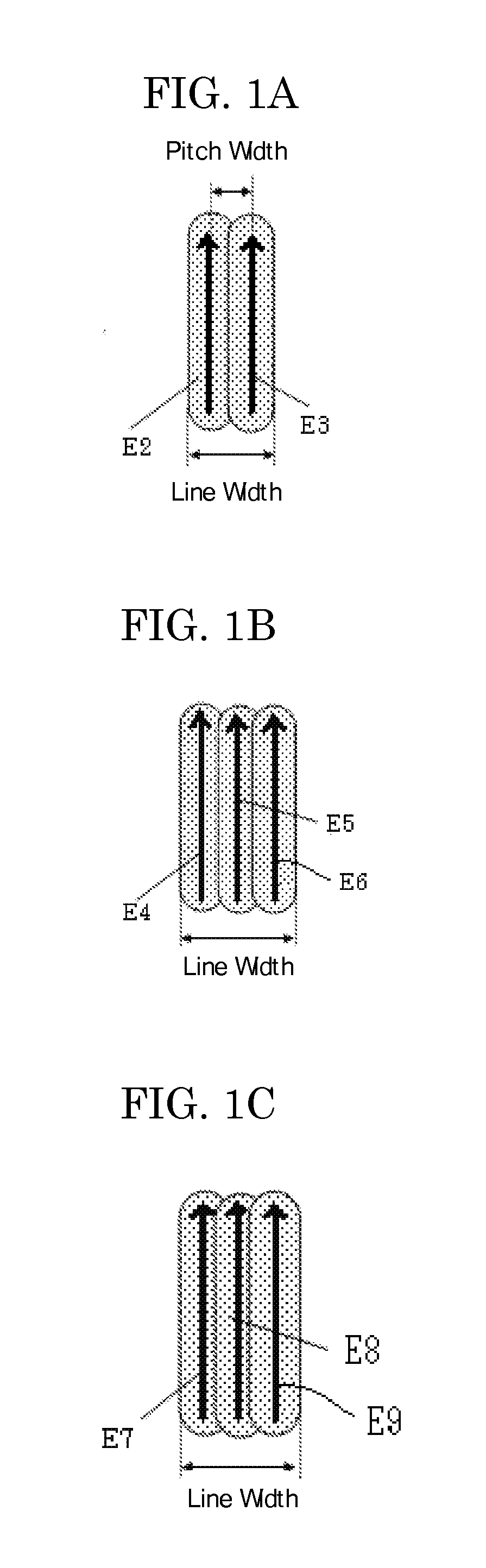
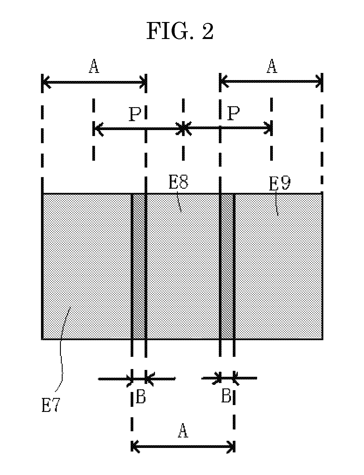
[0308]As a laser, a semiconductor laser, ES-6200-A manufactured by QPC Laser Inc. (center wavelength: 808 nm) was used, and controlled to emit one laser beam so that the output power was 27.3 W, the irradiation distance was 141 mm, the spot diameter was about 0.65 mm, the scanning speed was 2,000 mm / s, the irradiation energy was 21 mJ / mm2, and the line width was 0.42 mm. Then, the laser beam was made to scan a region of the thermoreversible recording medium obtained in Production Example 1 to form a first line written with laser beam (indicated by E7 in FIG. 2) as a line written first.

[0309]Next, another laser beam was controlled so that the output power was 22.2 W, the irradiation distance was 141 mm, the spot diameter was about 0.65 mm, the scanning speed was 2,000 mm / s, the irradiation energy was 17.1 mJ / mm2, and the width overlapped with the first written line was 0.22 mm (pitch: 0.20 mm), and the laser beam was made to scan the thermoreversible recording medium to form a second...


PUM

PropertyMeasurementUnit
Lengthaaaaaaaaaa
Lengthaaaaaaaaaa
Lengthaaaaaaaaaa

Abstract

The present invention provides an image processing method which includes recording an image by irradiating a recording medium with laser beams which are arrayed in parallel at predetermined intervals to heat the recording medium, so that the image is composed of a plurality of lines written with the laser beams on the recording medium, and wherein in the image recording, the plurality of lines written with the laser beams include a line written first and an overwritten line, a part of which is overlapped with the line written first; and the irradiation energy for the overwritten line is smaller than the irradiation energy for the line written first.

Description

BACKGROUND OF THE INVENTION[0001]1. Field of the Invention[0002]The present invention relates to an image processing method and an image processing apparatus for forming an image having an arbitrary line width with a plurality of image lines.[0003]2. Description of the Related Art[0004]Image recording and image erasing on a thermoreversible recording medium have been carried out so far by a contact method in which a heating source is brought into contact with a recording medium to heat the thermoreversible recording medium. As the heating source, in the case of image recording, a thermal head is generally used, and in the case of image erasing, a heat roller, a ceramic heater or the like is generally used.[0005]Such a contact image processing method has advantage in that, if a thermoreversible recording medium is a flexible material (e.g., a film, and paper sheet), an image can be uniformly recorded and erased by evenly pressing a heating source against a thermoreversible recording ...

Claims


Application Information

Patent Timeline
IPC IPC(8): B41J2/455
CPCB41J2/473B41M5/305B41J2/4753
Inventor ASAI, TOSHIAKIHOTTA, YOSHIHIKOISHIMI, TOMOMIKAWAHARA, SHINYA
Owner RICOH KK
Why Eureka
Try Eureka