
Isocyanate production process

a technology of isocyanate and production process, which is applied in the preparation of isocyanate derivatives, isocyanate purification/separation, organic chemistry, etc., can solve the problems of phosgene being extremely toxic, isocyanates having a detrimental effect on the weather resistance and heat resistance of polyurethane products, and the thermal decomposition of carbamic acid esters is susceptible to the simultaneous occurrence of various irreversible side reactions

Active Publication Date: 2011-04-21
ASAHI KASEI CHEM CORP
View PDF50 Cites 11 Cited by
  • Summary
  • Abstract
  • Description
  • Claims
  • Application Information

AI Technical Summary

Benefits of technology

[0092]According to the present invention, isocyanates can be produced without using phosgene, and continuous operation is possible over a long period of time.

Problems solved by technology

Firstly, this method requires the use of a large amount of phosgene as the raw material. Phosgene is extremely toxic and requires special handling precautions to prevent exposure of handlers thereof, and also requires special apparatuses to detoxify waste.
Secondly, since highly corrosive hydrogen chloride is produced in large amounts as a by-product of the phosgene method, in addition to requiring a process for detoxifying the hydrogen chloride, in many cases hydrolytic chlorine is contained in the isocyanates produced. Consequently, in the case of using isocyanates produced by the phosgene method, the isocyanates may have a detrimental effect on the weather resistance and heat resistance of polyurethane products.
On the other hand, thermal decomposition of carbamic acid esters is susceptible to the simultaneous occurrence of various irreversible side reactions such as thermal denaturation reactions undesirable for carbamic acid esters or condensation of isocyanates formed by the thermal decomposition.
In addition to these side reactions leading to a decrease in yield and selectivity of the target isocyanate, in the production of polyisocyanates in particular, these reactions may make long-term operation difficult as a result of, for example, causing the precipitation of polymeric solids that clog the reaction vessel.
In these processes, however, since there are cases in which, for example, the reaction mixture forms precipitates, polymeric substances and closed compounds in the reaction vessel and recovery apparatus due to the occurrence of side reactions as previously described, or these substances form substances that adhere to the walls of the reaction vessel, economic efficiency is poor in the case of producing isocyanates over a long period of time.
However, since there is no detailed description of production of the starting components, isolation or purification and arbitrary recovery of the solvent and catalyst mixture, the economic effects of this process were unable to be assessed.
However, this process is unable to achieve a yield of hexamethylene diisocyanate of 90% or more.
Thus, purification of the hexamethylene diisocyanate by distillation is still required, and there are numerous cases in which yield loss increases.
Thus, although it is possible to remove by-products from the bottom of the reaction vessel, the problem of the case of substances adhering to the walls of the reaction vessel as previously described remains, and problems regarding long-term operation are unresolved.
In addition, there is no description regarding the industrial use of the removed residual substances (containing large amounts of useful components).
Examples of disadvantages of this process may include a decrease in the space time yield of polyisocyanate due to the use of a circulating solvent, and a large energy requirement, including recovery of the solvent.
Moreover, since the assistant used is volatile under the reaction conditions, contamination of the decomposition products can occur.
In addition, since there is a large amount of residual substances formed relative to the polyisocyanate formed, there is some doubt regarding economic efficiency and reliability as an industrial process.
In addition, there is no description of a continuous method accompanying recovery of rebonded or partially decomposed carbamates, nor is there any mention of post-treatment of solvent containing by-products and catalyst.
Isocyanate groups formed in useful products react with residual urethane, frequently resulting in the formation of comparatively high molecular weight by-products that decrease yield.

Method used

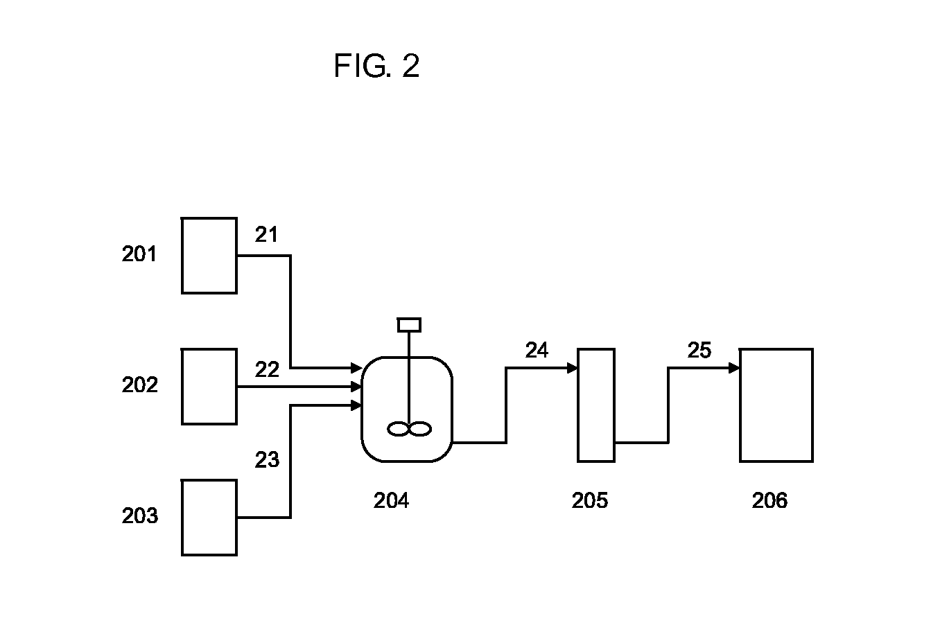
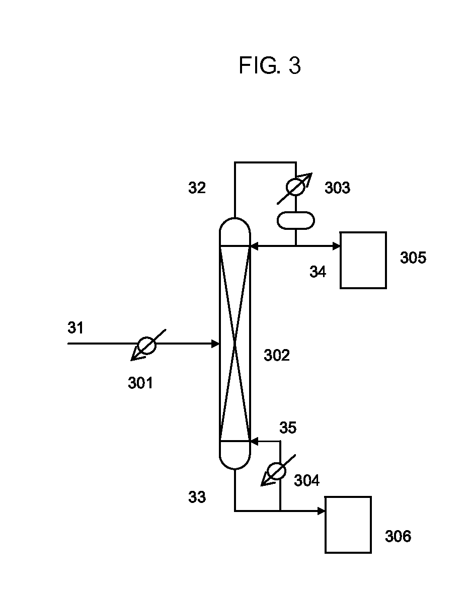

Image

  • Isocyanate production process
  • Isocyanate production process
  • Isocyanate production process

Examples


reference example 1

Production of Bis(3-methylbutyl)Carbonate

Step (1-1): Production of Dialkyl Tin Catalyst

[0312]625 g (2.7 mol) of di-n-butyl tin oxide (Sankyo Organic Chemicals Co., Ltd., Japan) and 2020 g (22.7 mol) of 3-methyl-1-butanol (Wako Pure Chemical Industries, Ltd., Japan) were placed in a 5000 mL volumetric pear-shaped flask. The flask was connected to an evaporator (R-144, Shibata Co., Ltd., Japan) to which was connected an oil bath (OBH-24, Masuda Corp., Japan) equipped with a temperature controller, a vacuum pump (G-50A, Ulvac Inc., Japan) and a vacuum controller (VC-10S, Okano Seisakusho Co., Ltd.). The purge valve outlet of this evaporator was connected to a line containing nitrogen gas flowing at a normal pressure. After closing the purge valve of the evaporator to a reduce pressure inside the system, the purge valve was opened gradually to allow nitrogen to flow into the system and return to the normal pressure. The oil bath temperature was set to be about 145° C., the flask was imm...

reference example 2

Production of Dibutyl Carbonate

Step (II-1): Production of Dialkyl Tin Catalyst

[0314]692 g (2.78 mol) of di-n-butyl tin oxide and 2001 g (27 mol) of 1-butanol (Wako Pure Chemical Industries, Ltd., Japan) were placed in a 3000 mL volumetric pear-shaped flask. The flask containing a mixture in the form of a white slurry was connected to an evaporator to which was connected an oil bath equipped with a temperature controller, a vacuum pump and a vacuum controller. The purge valve outlet of the evaporator was connected to a line containing nitrogen gas flowing at normal pressure. After closing the purge valve of the evaporator to reduce pressure inside the system, the purge valve was opened gradually to allow nitrogen to flow into the system and return to normal pressure. The oil bath temperature was set to be 126° C., the flask was immersed in the oil bath and rotation of the evaporator was started. After heating for about 30 minutes at a normal pressure with the purge valve of the evapo...

reference example 3

Production of Bis(2-ethylbutyl)Carbonate

Step (III-1): Production of Dialkyl Tin Catalyst

[0316]893 g (2.48 mol) of di-n-octyl tin oxide (Sankyo Organic Chemicals Co., Ltd., Japan) and 2403 g (23.6 mol) of 2-ethyl-1-butanol were placed in a 5000 mL volumetric pear-shaped flask. The flask was connected to an evaporator to which was connected an oil bath equipped with a temperature controller, a vacuum pump and a vacuum controller. The purge valve outlet of the evaporator was connected to a line containing nitrogen gas flowing at a normal pressure. After closing the purge valve of the evaporator to reduce pressure inside the system, the purge valve was opened gradually to allow nitrogen to flow into the system and return to the normal pressure. The oil bath temperature was set to be about 165° C., the flask was immersed in the oil bath and rotation of the evaporator was started. After heating for about 40 minutes in the presence of nitrogen at atmospheric pressure with the purge valve o...


PUM

PropertyMeasurementUnit
Temperatureaaaaaaaaaa
Fractionaaaaaaaaaa

Abstract

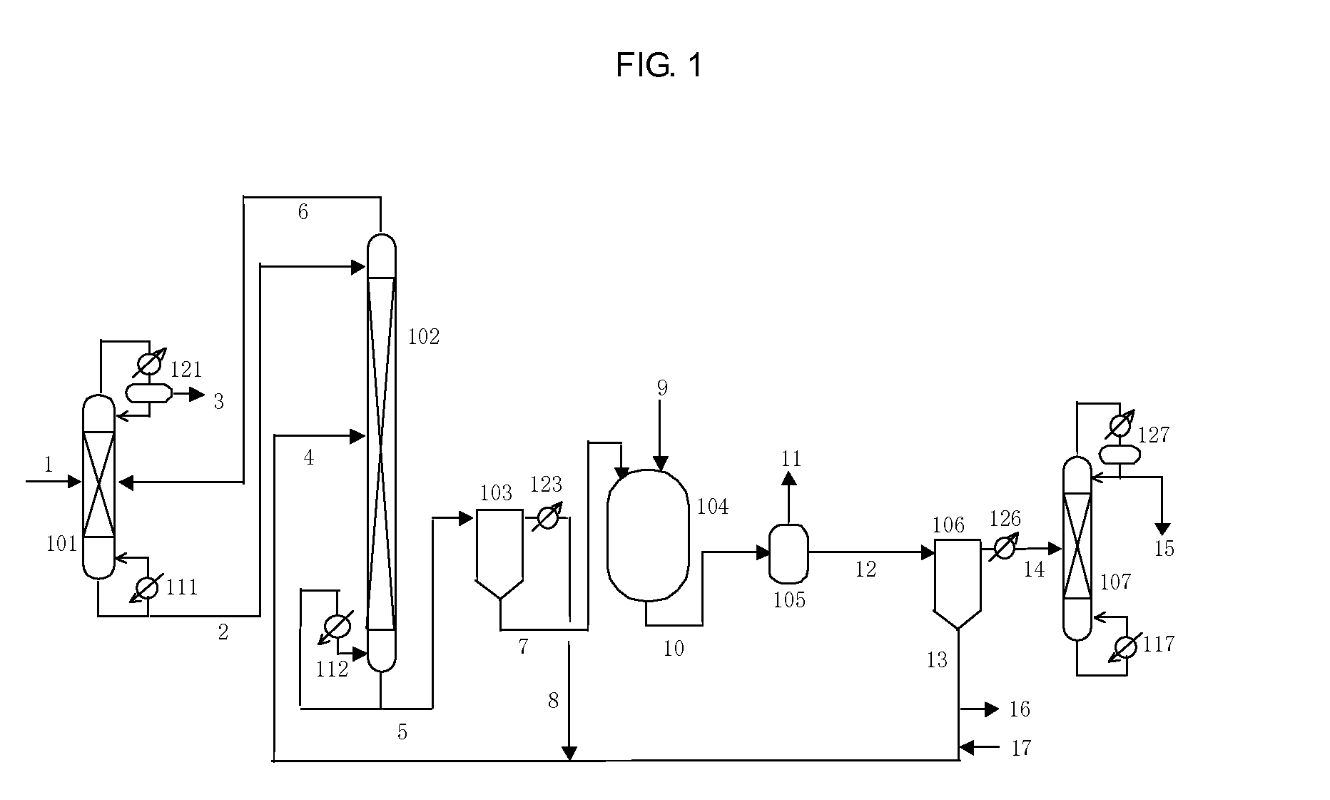
An object of the present invention is to provide a process that enables isocyanate to be produced stably over a long period of time and at high yield without encountering problems of the prior art during production of isocyanate without using phosgene. The present invention discloses a process for producing an isocyanate by subjecting a carbamic acid ester to a thermal decomposition reaction, including the steps of: recovering a low boiling point component in a form of a gaseous phase component from a thermal decomposition reaction vessel in which the thermal decomposition reaction is carried out; recovering a liquid phase component containing a carbamic acid ester from a bottom of the thermal decomposition reaction vessel; and supplying all or a portion of the liquid phase component to an upper portion of the thermal decomposition reaction vessel.

Description

TECHNICAL FIELD [0001]The present invention relates to an isocyanate production process.BACKGROUND ART [0002]Isocyanates are widely used as raw materials of such products as polyurethane foam, paints, adhesives and the like. The main industrial production process of isocyanates involves reacting amine compounds with phosgene (phosgene method), and nearly the entire amount of isocyanates produced throughout the world are produced according to the phosgene method. However, the phosgene method has numerous problems.[0003]Firstly, this method requires the use of a large amount of phosgene as the raw material. Phosgene is extremely toxic and requires special handling precautions to prevent exposure of handlers thereof, and also requires special apparatuses to detoxify waste.[0004]Secondly, since highly corrosive hydrogen chloride is produced in large amounts as a by-product of the phosgene method, in addition to requiring a process for detoxifying the hydrogen chloride, in many cases hyd...

Claims


Application Information

Patent Timeline
IPC IPC(8): C07C263/04
CPCC07C263/04C07C263/18C07C2101/14C07C265/14C07C2601/14C07C263/00C07C265/00C07C265/02
Inventor SHINOHATA, MASAAKIMIYAKE, NOBUHISA
Owner ASAHI KASEI CHEM CORP
Learn More