
Pump cassette and methods for use in medical treatment system using a plurality of fluid lines

a technology of fluid line and pump cassette, which is applied in the direction of machines/engines, liquid fuel engines, positive displacement liquid engines, etc., can solve the problems of dampening the acceptance of apd as an alternative by the general public, and unable to meet the requirements of capd or other methods, so as to reduce the noise or vacuum of the pneumatic pressure or the effect of system compactness and reduced noise generation

Active Publication Date: 2011-04-21
DEKA PROD LLP
View PDF104 Cites 127 Cited by
  • Summary
  • Abstract
  • Description
  • Claims
  • Application Information

AI Technical Summary

Benefits of technology

The invention relates to a disposable fluid handling cassette for use in medical applications such as peritoneal dialysis. The cassette includes a body with a pump chamber and multiple flowpaths for fluid. A membrane is attached to the body and over the pump chamber, and a pump chamber portion has an unstressed shape that allows it to move fluid in the pump chamber. The cassette can be used with a reusable automated peritoneal dialysis cycler device. The technical effects of the invention include improved fluid handling in medical applications, reduced risk of blocking fluid lines, and improved efficiency of the dialysis process.

Problems solved by technology

IPD can also be used when a patient requires PD, but cannot undertake the responsibilities of CAPD or otherwise do it at home.
Still, the complexity and size of past machines and associated disposables for various APD modalities have dampened widespread patient acceptance of APD as an alternative to manual peritoneal dialysis methods.

Method used


Image

  • Pump cassette and methods for use in medical treatment system using a plurality of fluid lines
  • Pump cassette and methods for use in medical treatment system using a plurality of fluid lines
  • Pump cassette and methods for use in medical treatment system using a plurality of fluid lines

Examples


Embodiment Construction

[0138]Although aspects of the invention are described in relation to a peritoneal dialysis system, certain aspects of the invention can be used in other medical applications, including infusion systems such as intravenous infusion systems or extracorporeal blood flow systems, and irrigation and / or fluid exchange systems for the stomach, intestinal tract, urinary bladder, pleural space or other body or organ cavity. Thus, aspects of the invention are not limited to use in peritoneal dialysis in particular, or dialysis in general.

[0139]APD System

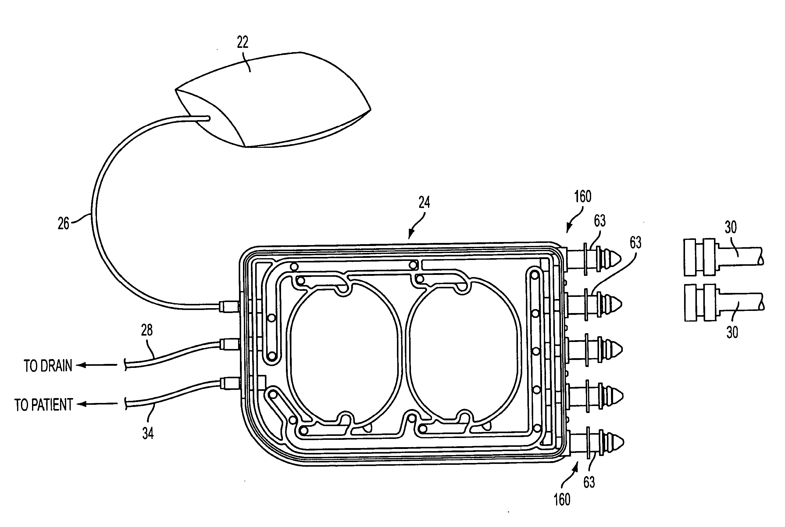
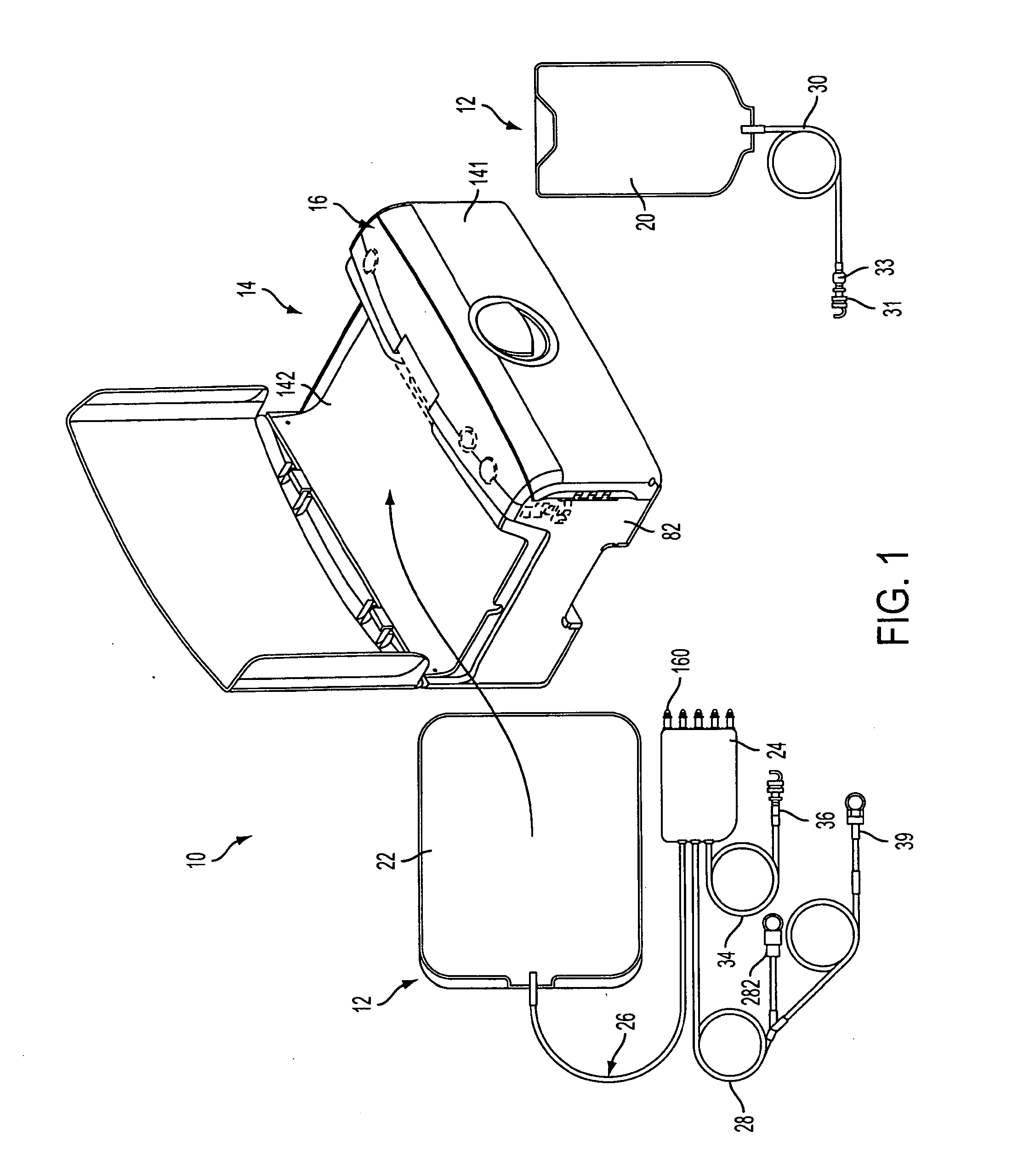
[0140]FIG. 1 shows an automated peritoneal dialysis (APD) system 10 that may incorporate one or more aspects of the invention. As shown in FIG. 1, for example, the system 10 in this illustrative embodiment includes a dialysate delivery set 12 (which, in certain embodiments, can be a disposable set), a cycler 14 that interacts with the delivery set 12 to pump liquid provided by a solution container 20 (e.g., a bag), and a control system 16 (e.g...


PUM


Abstract

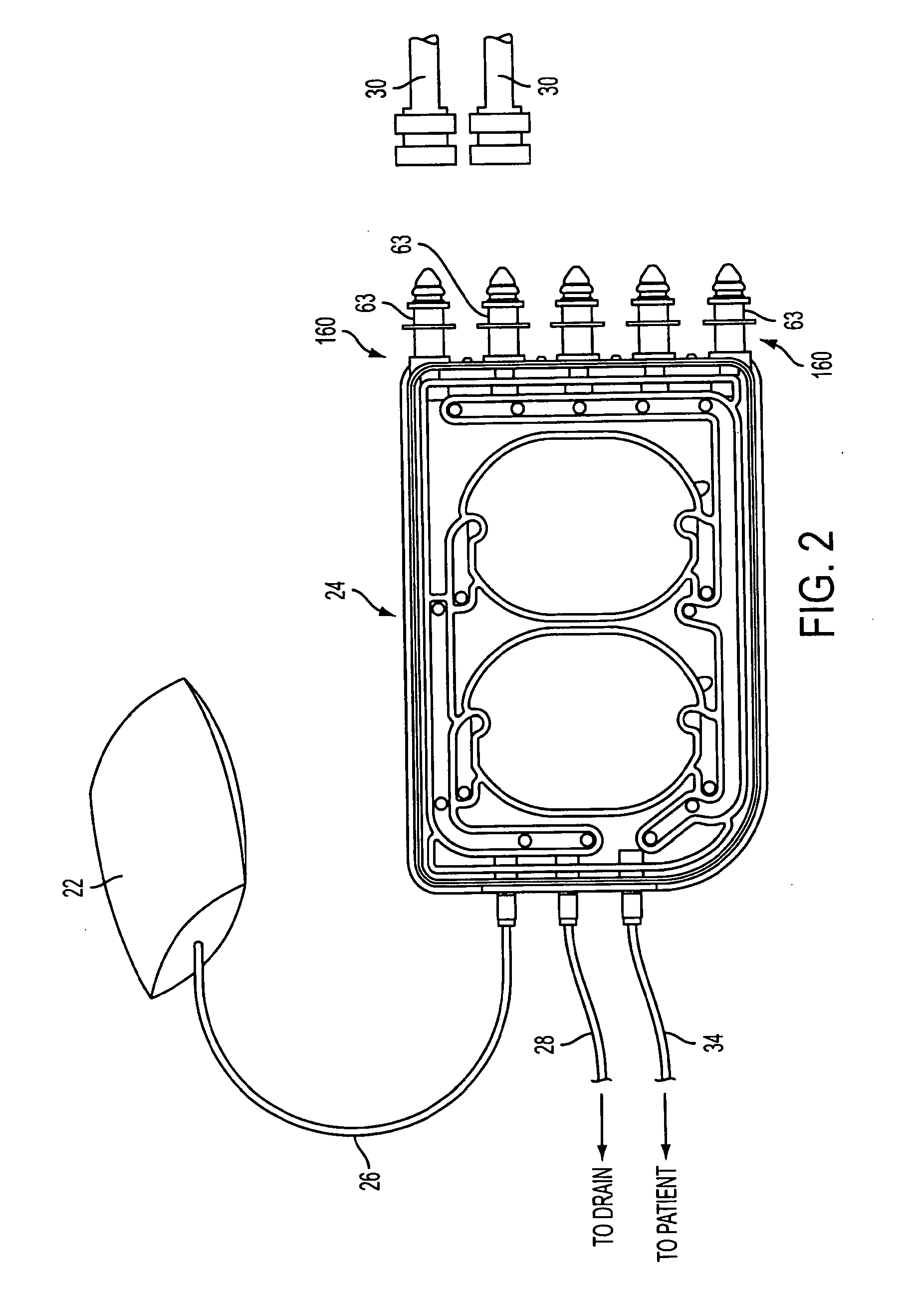
A fluid handling cassette (24), such as that useable with an APD cycler device or other infusion apparatus, may include a generally planar body having at least one pump chamber (181) formed as a depression in a first side of the body and a plurality of flowpaths for fluid that includes a channel. A patient line port may be arranged for connection to a patient line (34) and be in fluid communication with the at least one pump chamber via at least one flowpath, and an optional membrane (15) may be attached to the first side of the body over the at least one pump chamber. In one embodiment, the membrane may have a pump chamber portion (151) with an unstressed shape that generally conforms to the pump chamber depression in the body and is arranged to be movable for movement of fluid in the useable space of the pump chamber. One or more spacers (50) may be provided in the pump chamber to prevent a pump membrane from contacting an inner wall of the pump chamber. Patient, drain (28) and / or heater bag lines (26) may be positioned to be separately occludable in relation to one or more solution lines (30) that are connectable to the cassette.

Description

BACKGROUND[0001]Peritoneal Dialysis (PD) involves the periodic infusion of sterile aqueous solution (called peritoneal dialysis solution, or dialysate) into the peritoneal cavity of a patient. Diffusion and osmosis exchanges take place between the solution and the bloodstream across the natural body membranes. These exchanges transfer waste products to the dialysate that the kidneys normally excrete. The waste products typically consist of solutes like sodium and chloride ions, and other compounds normally excreted through the kidneys like urea, creatinine, and water. The diffusion of water across the peritoneal membrane during dialysis is called ultrafiltration.[0002]Conventional peritoneal dialysis solutions include dextrose in concentrations sufficient to generate the necessary osmotic pressure to remove water from the patient through ultrafiltration.[0003]Continuous Ambulatory Peritoneal Dialysis (CAPD) is a popular form of PD. A patient performs CAPD manually about four times a...

Claims


Application Information

Patent Timeline
Patent Type & Authority Applications(United States)
IPC IPC(8): A61M1/28A61M5/142
CPCA61M1/28A61M39/1011A61M39/105A61M39/20A61M39/28A61M2205/3379A61M2209/08A61M1/281A61M1/288A61M2205/12A61M5/16813A61M39/281A61M2205/128A61M2205/502A61M2205/3334F04B43/02F04B43/08F04B43/086A61M2205/3331G16H40/63G16H20/40A61M2205/6036F04B43/0054F04B53/22F04B43/073Y02A90/10A61M1/166A61M2205/36A61M1/155A61M1/153A61M1/1565A61M1/159A61M1/1524A61M1/1522A61M1/1561A61M5/145A61M1/1623A61M1/1601A61M1/1631A61M1/1629A61M1/1694A61M1/282A61M2039/1066A61M2205/122A61M2205/123A61M2205/127A61M2205/13A61M2205/14A61M2205/3306A61M1/34A61M5/16809A61M5/16827A61M1/16A61M1/14A61M2205/121
Inventor MCGILL, DAVID W.DALE, JAMES D.HELMORE, SIMON C.LANIGAN, RICHARD J.DEMERS, JASO A.KAMEN, DEAN
Owner DEKA PROD LLP
Learn More