
Method to prepare a stable transparent electrode

a metal electrode, stable technology, applied in the direction of electroluminescent light sources, solid-state diffusion coatings, coatings, etc., can solve the problems of inability to protect the ca layer from oxidation, inability to easily be obtained in large quantities and thus expensive, and incompatibility with some active materials

Active Publication Date: 2011-05-19
FUNDACIO INST DE CIENCIES FOT NIQUES +1
View PDF7 Cites 5 Cited by
  • Summary
  • Abstract
  • Description
  • Claims
  • Application Information

AI Technical Summary

Benefits of technology

[0041]In view of the above exposed it can be seen that the method of the present invention presents the important advantage of providing stable and transparent conductive electrodes which find many applications due to their simple and low cost method of fabrication and their intrinsic technical characteristics. In this sense it is known that in devices such as photovoltaic cells, organic light emitting, integrated electro-optic modulators, lasers and photo-detectors, transparent conductive electrodes are key elements, and are combined with other materials. The stability of the electrodes obtained according to the method of the invention is of outmost importance to maintain the performance of the devices over time, in particular under demanding and changing environmental conditions. In addition since during the fabrication process, after the transparent conductive electrode is deposited, subsequent processing (e.g. those required to complete the device structure) can alter significantly the electrodes properties, the stable electrodes prepared according to the present method are also very interesting from this point of view.

Problems solved by technology

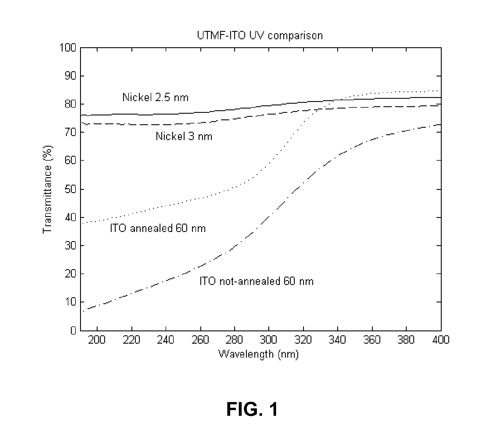
Despite possessing large electrical conductivity and optical transparency from the visible to the infrared, TCOs present several drawbacks such as the requirement of high temperature (several hundreds of ° C.) post deposition treatments to improve mainly their electrical properties, their strong electrical and optical dependence on the doping control and their multicomponent structure that can lead to incompatibilities with some active materials.
Often, such as in the case of ITO, they are made of elements (In) which are not easily available in large quantities and thus expensive.
In fact in that reference it is said that also a double layer structure of Ca—Al has been tried for the purpose of reaching stability but the Al layer seems to be unable to protect the Ca layer from oxidation.
However, given their metallic nature, UTMFs can easily degrade through oxidation, thus changing their electrical and optical properties.
To avoid oxidation and stability issues ultra thin noble metals have been used as transparent electrodes, such as gold, platinum and palladium but this is an expensive alternative.

Method used


Image

  • Method to prepare a stable transparent electrode
  • Method to prepare a stable transparent electrode
  • Method to prepare a stable transparent electrode

Examples


example 1

Method, Ni-UTMF Obtained and its Characterization

[0043]A 3.4 nanometers thick nickel ultrathin metal film was deposited on a double-side polished BK7 substrate using an ATC ORION 3 HV Sputtering DC System. The sputtering process was performed at room temperature in a pure argon (Ar) atmosphere. Argon pressure was set to 8 mTorr and 200 W DC power electric field was used.

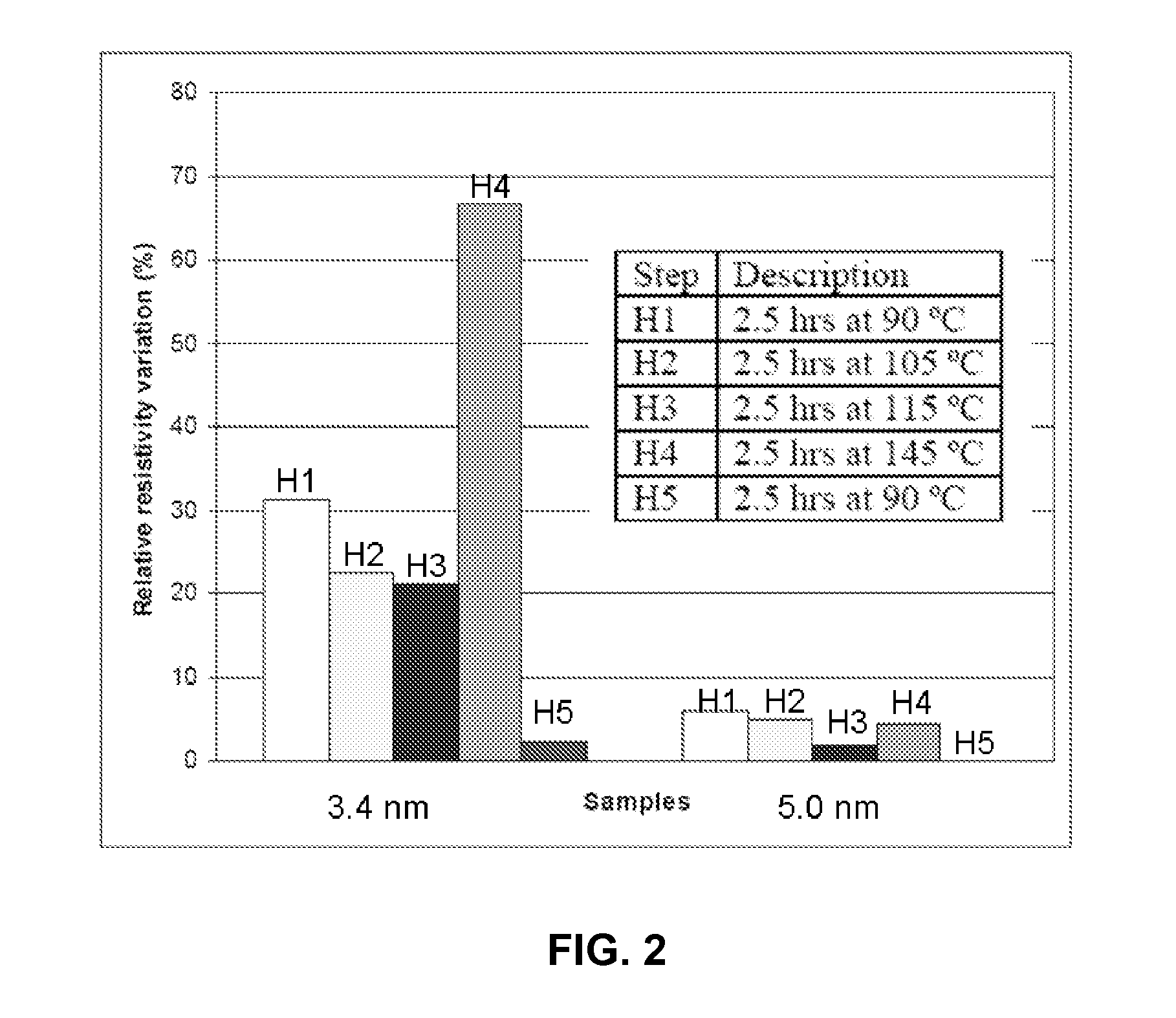
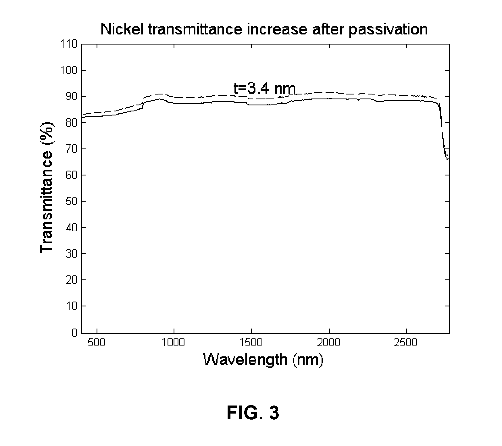
[0044]The electrical resistivity of the film at room temperature was measured straight after deposition and twelve days after the film was deposited, always being kept in ambient atmosphere. A Cascade Microtech 44 / 7S Four Point Probe and a Keithley 2001 multimeter were used for measuring sheet resistance. The sheet resistance (Rs), i.e. the resistance of a square like sheet of layer, is measured in Ω / and is related to the electrical resistivity (ρ) measured in Ω·m through the following relation: Rs=ρ / t with t the thickness of the layer in m. The resistivity of the layer was thus obtained as the ratio between sheet r...

example 2

Method, Ni-UTMF Obtained and its Characterization

[0047]The method of the invention comprised depositing on a substrate a 6 nanometers thick nickel ultrathin metal film. The film was grown on a double-side polished BK7 substrate using an ATC ORION 3 HV Sputtering DC System. The sputtering process was performed at room temperature in a pure argon (Ar) atmosphere. Argon pressure was set to 8 mTorr and 200 W DC power electric field was used.

[0048]The electrical resistivity and the optical transmittance of the film are then measured as it is described in the previous example.

[0049]The film undergoes a thermal treatment at about 120° C. and is subjected to a continuous neutral (unionized) oxygen flux of about 20 sccm with kinetic energy of about 130 eV. After about 10 minutes, from electrical resistivity measurements and thickness change measurements, it was found that the formed oxide thickness was about 2.5 nm.

[0050]The Ni-UTMF so obtained was stable.


PUM

PropertyMeasurementUnit
Temperatureaaaaaaaaaa

Abstract

The present application discloses a method for producing a stable ultra thin metal film that comprises the following steps: a) deposition, on a substrate, of an ultra thin metal film, such as an ultra thin film of nickel, chromium, aluminium, or titanium; b) thermal treatment of the ultra thin metal film, optionally in combination with an O2 treatment; and c) obtaining a protective oxide layer on top of the ultra thin metal film.

Description

FIELD OF THE INVENTION[0001]The present invention relates to optically transparent and electrically conductive metal electrodes based on ultra thin metal films (UTMFs) for optoelectronic applications.BACKGROUND OF THE INVENTION[0002]Transparent electrodes, i.e. films which can conduct electricity and at the same time transmit light, are of crucial importance for many optical devices, such as photovoltaic cells [Claes G. Granqvist “Transparent conductors as solar energy materials: A panoramic review” Solar Energy Materials & Solar Cells 91 (2007) 1529-1598], organic light emitting diodes [Ullrich Mitschke and Peter Bäuerle, “The electroluminescence of organic materials” J. Mater. Chem., 2000, 10, 1471], integrated electro-optic modulators [CM Lee et al., “Minimizing DC drift in LiNbO3 waveguide devices”, Applied Physics Lett. 47, 211 (1985)], laser displays [C. A. Smith “A review of liquid crystal display technologies, electronic interconnection and failure analysis Circuit” World Vo...

Claims


Application Information

Patent Timeline
IPC IPC(8): C23C8/10B05D5/12
CPCH01L33/42H01L31/022408H01L31/022466H05B33/26H10K50/805
Inventor PRUNERI, VALERIOMARTINEZ MONTBLANCH, LUISGIURGOLA, STEFANOVERGANI, PAOLO
Owner FUNDACIO INST DE CIENCIES FOT NIQUES
Learn More