Plasma-Deposited Electrically Insulating, Diffusion-Resistant and Elastic Layer System

a technology of diffusion resistance and elastic layer, applied in the field of multi-layer system, can solve the problems of silicon nitride layer, not so well suited to use in aqueous solution, and the electrode diffusion barrier in an aqueous solution is not so good,

Inactive Publication Date: 2011-05-26
TECH UNIV KAISERSLAUTERN
View PDF14 Cites 23 Cited by
  • Summary
  • Abstract
  • Description
  • Claims
  • Application Information

AI Technical Summary

Problems solved by technology

Layer systems of this type are not so well suited to use in an aqueous solution, in particular for suppressing an ion current in the potential gradient, as the resistance of SiO2 decreases under moisture as a result of incipient hydrolysis processes.
The silicon nitride layers (for example Si3N4), which are likewise used in semiconductor structures, also tend to be unsuitable as diffusion barriers on electrodes in an aqueous solution.
The laminate described in U.S. Pat. No. 6,491,798 B2, which is made up of sputtered carbon layers, does not have sufficient diffusion resistance.
Drawbacks of the layer system according to U.S. Pat. No. 6,891,155 include the high layer thickness while having at the same time a small number of layers; this results in the formation of cracks under loading and expansion.
In particular, this system is not suitable for use on flexible substrates.

Method used


Image

  • Plasma-Deposited Electrically Insulating, Diffusion-Resistant and Elastic Layer System
  • Plasma-Deposited Electrically Insulating, Diffusion-Resistant and Elastic Layer System
  • Plasma-Deposited Electrically Insulating, Diffusion-Resistant and Elastic Layer System

Examples


exemplary embodiment 1

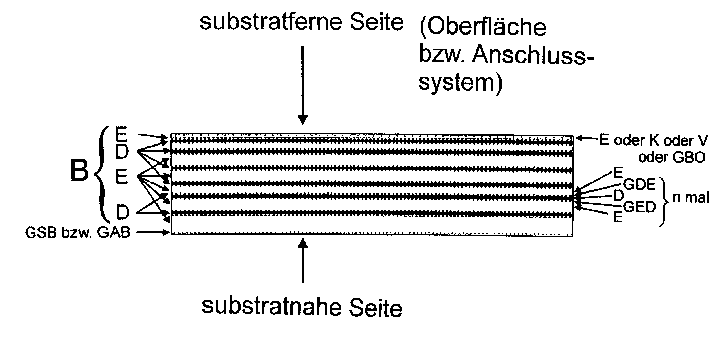
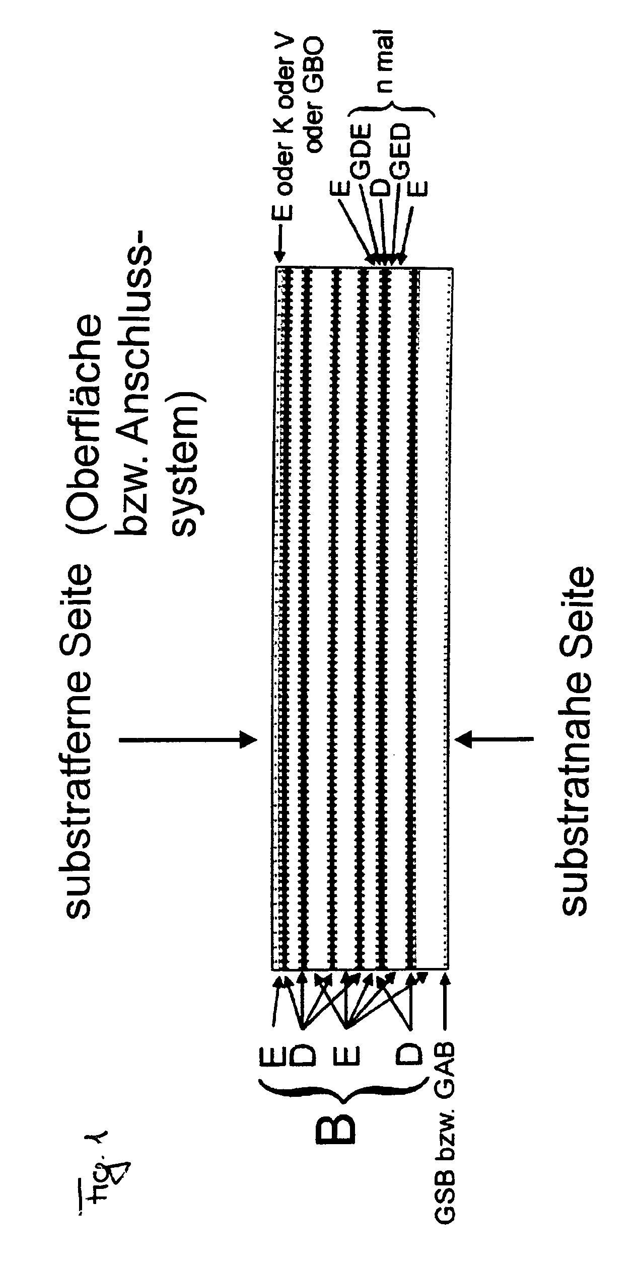
[0060 made up of rf plasma-deposited, water-containing, amorphous carbon layers of various composition and layer properties:

LayerLayertypeMaterialStoichiometrythicknessSurfaceK and Va-CH20% H40 nmcontentEa-CH40% H30 nmcontentDa-CH35% H20 nmcontentEa-CH40% H30 nmcontentDa-CH35% H20 nmcontentEa-CH40% H30 nmcontentDa-CH35% H20 nmcontentEa-CH40% H30 nmcontentDa-CH35% H20 nmcontentEa-CH40% H30 nmcontentDa-CH35% H20 nmcontentEa-CH40% H30 nmcontentDa-CH35% H20 nmcontentEa-CH40% H30 nmcontentGSBGradient PLCH (close to the25substrate) on a-C:H (toward E)Substrate

[0061]Exemplary Embodiment 1 ensures the diffusion resistance, described in the present document, on the substrates parylene, polyethylene (PE), polyurethane (PU) and polypropylene (PP). The gradient transition layers GED and GDE form the transition between the a-C:H layers of various stoichiometry and have layer thicknesses of about 7 nm. Are not listed in the table. Exemplary Embodiment 1, described in the present document and appl...

exemplary embodiment 2

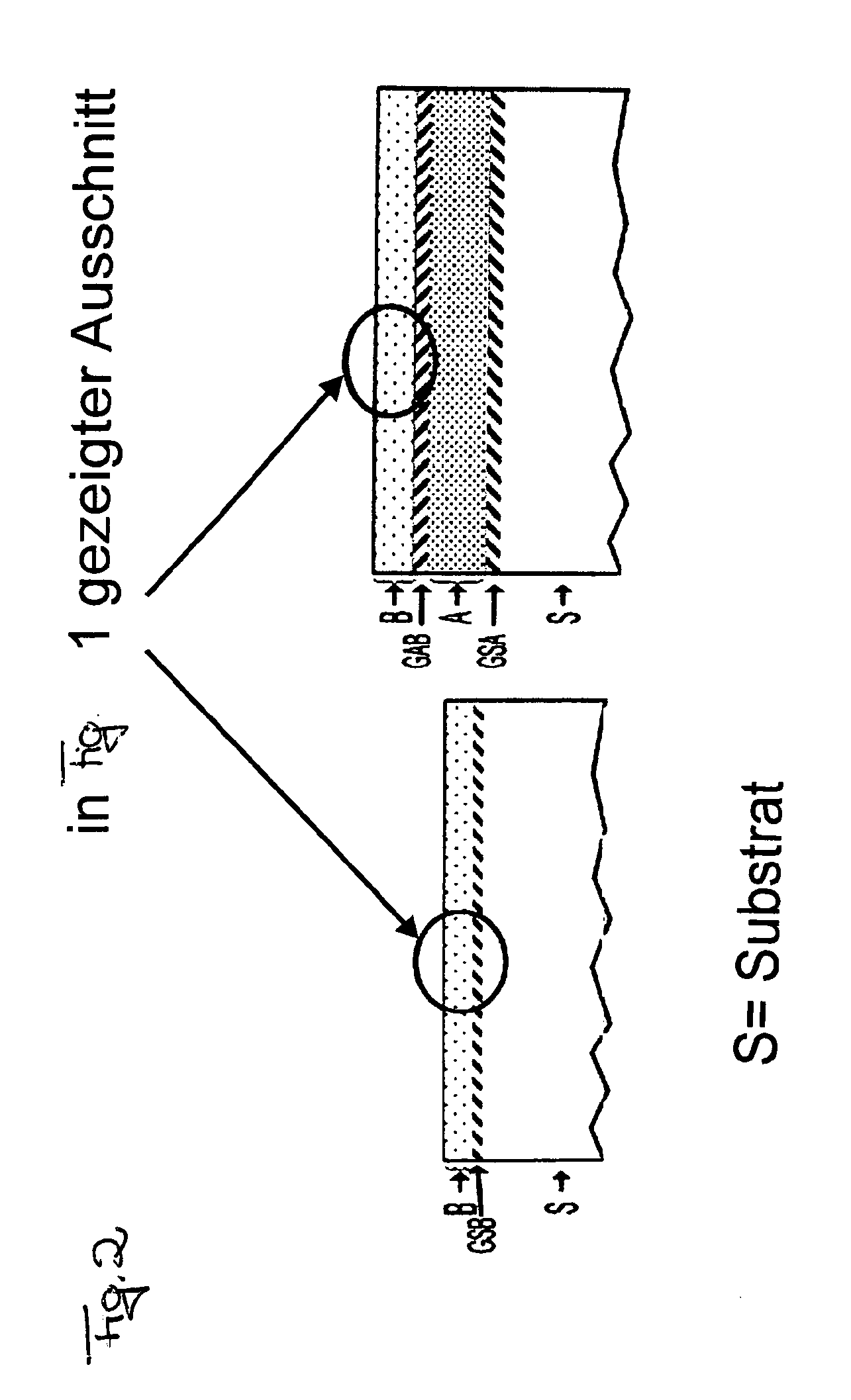
[0062 made up of rf plasma-deposited, water-containing, amorphous carbon layers of various composition and layer properties and also plasma-polymerised layers

LayerLayertypeMaterialStoichiometrythicknessSurfaceK and Va-CH20% H content40nmEa-CH40% H content30nmDa-CH35% H content20nmEa-CH40% H content30nmDa-CH35% H content20nmEa-CH40% H content30nmDa-CH35% H content20nmEa-CH40% H content30nmDa-CH35% H content20nmEa-CH40% H content30nmDa-CH35% H content20nmEa-CH40% H content30nmGABGradient PLCH (close to25the substrate) on a-C:H(toward E)APlasma-polymerised layerAccording to H. Yasuda, T. Hsu,500nmSurface Science 76(1978) 232GSAReactive plasmaChemically modified10nmtreatment with oxygensubstrate materialSubstrate

[0063]Exemplary Embodiment 2 ensures the diffusion resistance, described in the present document, on the substrates parylene, polyethylene (PE), polyurethane (PU) and polypropylene (PP). The gradient transition layers GED and GDE form the transition between the a-C:H layers of v...


PUM

PropertyMeasurementUnit
wavelengthsaaaaaaaaaa
resistanceaaaaaaaaaa

Abstract

A multilayer system on a substrate, the multilayer system being applied to the substrate by plasma deposition, characterized in that the multilayer system is configured such that it has substantial diffusion resistance to ions in an aqueous solution, wherein the current produced by the diffusion of the ions with the connection of an electric field gradient of more than 104V/m, preferably more than 105V/m, most preferred more than 107V/m is IIon<6.5×10⁻⁸ A/cm2, preferably IIon<6.5×10⁻¹⁰ A/cm2, particularly IIon<1×10⁻¹² A/cm2.

Description

FIELD OF THE INVENTION[0001]The invention relates to a multilayer system on a substrate, in particular a multilayer system which is applied to the substrate with the aid of plasma deposition. Furthermore, the invention relates to the use of a multilayer system of this type.PRIOR ART[0002]Diffusion barriers are of very great interest for a broad range of applications. The number of developments and publications in this field is correspondingly large. Most relate to the diffusion suppression of oxygen and moisture, for example on PET beverage bottles or organic light emitting diode (OLED) systems. The migration of charge carriers in solid layer systems is particularly important in the semiconductor industry and electronics, where layers are accordingly often used as diffusion barriers (albeit in a dry environment) between individual functional layers, for example of a transistor.[0003]Diffusion barriers based on silicon dioxide, which under dry conditions has a resistance of >1016Ω...

Claims


Application Information

Patent Timeline
Patent Type & Authority Applications(United States)
IPC IPC(8): G02B1/12B32B9/04H01L51/52A61N1/375C23C16/513G02B5/20
CPCA61N1/05A61N1/375Y10T428/30C23C16/45523H01L51/5237C23C16/26Y10T428/31504A61N1/37512H10K50/8445
Inventor BUSCH, HEINZ WERNERGRABOWY, UDO HEINRICHKLEINEN, LISA
Owner TECH UNIV KAISERSLAUTERN
Why Eureka
Try Eureka