

Membrane-electrode assembly and fuel cell using the same
a technology of membrane electrolectrodes and fuel cells, applied in the manufacture of cell components, final product manufacturing, electrochemical generators, etc., can solve the problems of low initial cell performance, achieve high output power, improve gas diffusivity, and increase catalyst utilization in anodes and cathodes
- Summary
- Abstract
- Description
- Claims
- Application Information
AI Technical Summary
Benefits of technology
Problems solved by technology
Method used
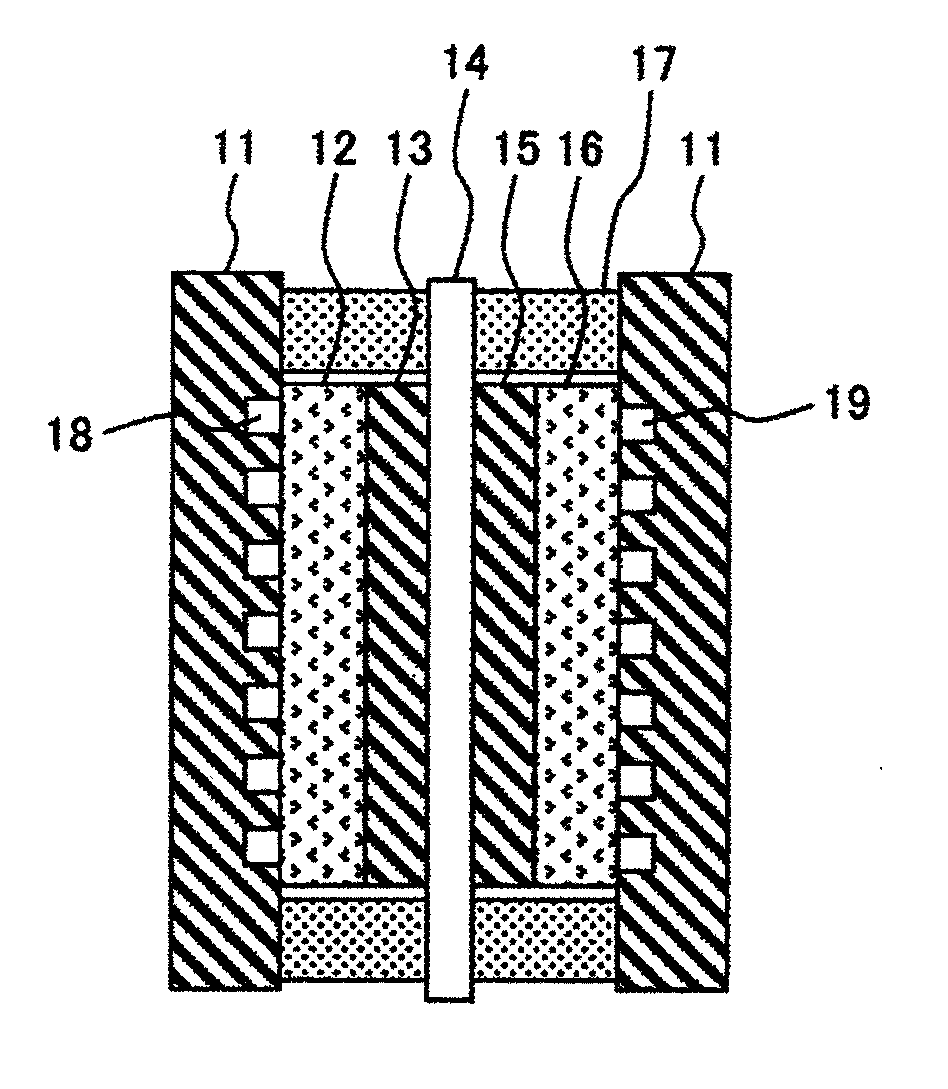
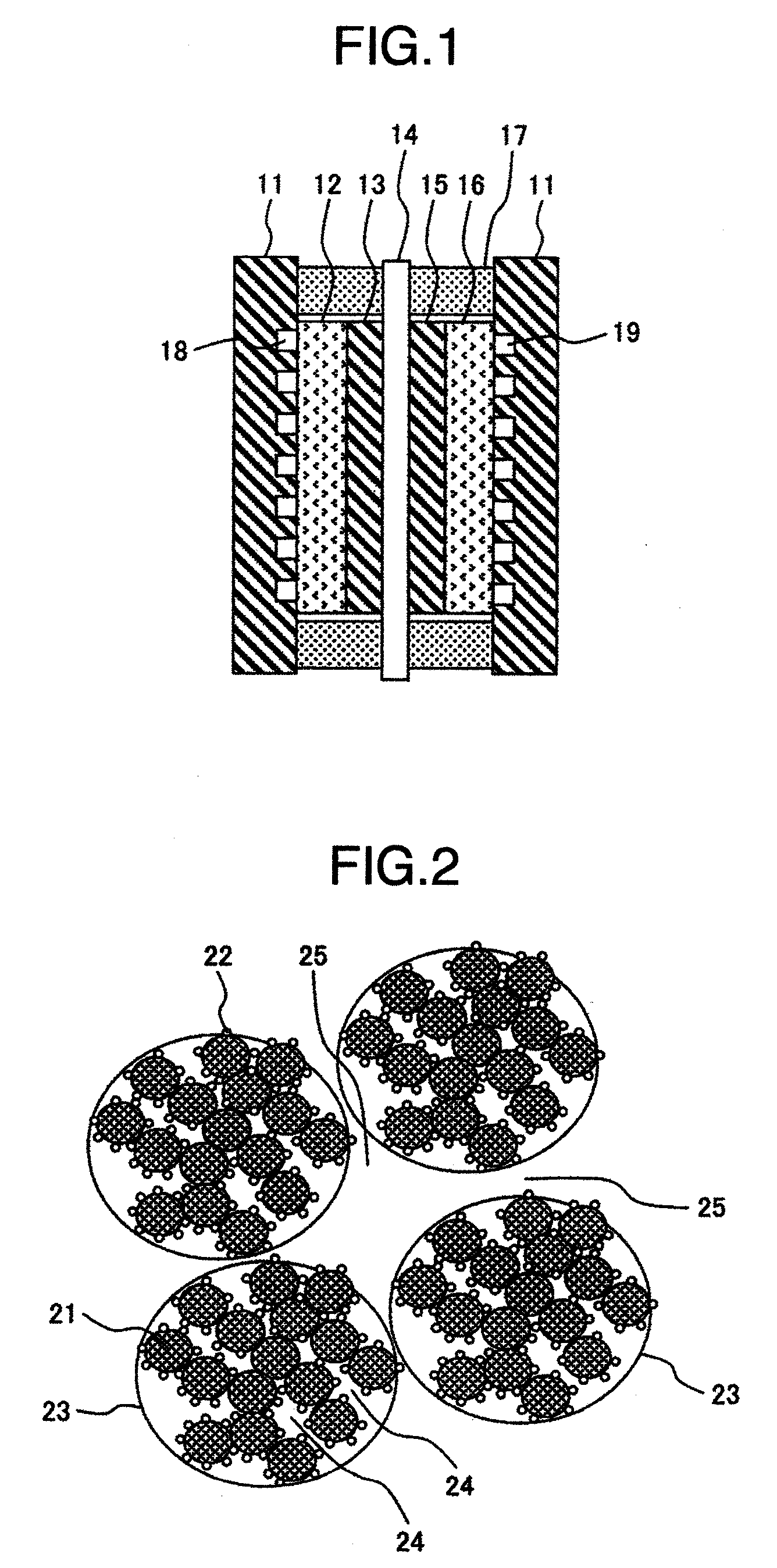
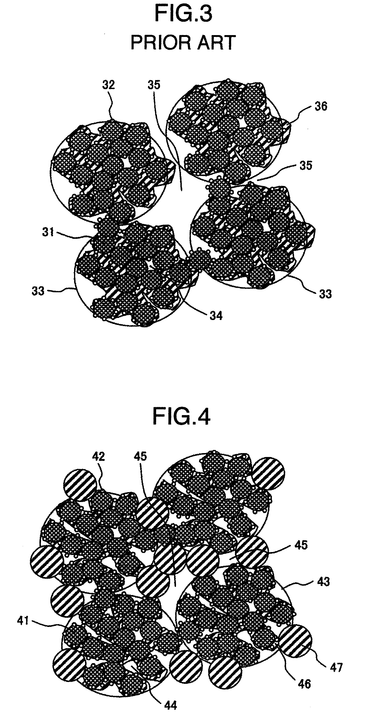
Image

Examples
preparation of example 1
[0158](2-1)
[0159]The Polymer B synthesized in the above-described (1-1) was dried at 120° C. for 2 hours. This Polymer B (10 g) was taken out, and a mixture (90 g) of 1-propanol, 2-propaol and water in a weight ratio of 40:40:20 was dropped thereto. A sample bottle containing this mixture was placed in a water bath equipped with an ultrasonic generator, and irradiated with an ultrasonic wave to the disperse Polymer B.
[0160]Although the mixture of 1-propanol, 2-propaol and water was used as a solvent in this Example, a mixture further containing 1-methyl-2-pyrroridone may be used as the solvent.
(2-2)
[0161]To the dispersion liquid of Polymer B prepared in the above-described (2-1), a 0.2 M aqueous sodium hydroxide solution was added and neutralized the pH of the dispersion liquid, and then dispersed particles of Polymer B was formed in the liquid. This liquid was referred to as dispersion liquid B. The size of the dispersed particles in dispersion liquid B was measured using a dynamic...
preparation of example 2
[0166](3-1)
[0167]Sulfonated polyethersulfone having a smaller molecular weight than the Polymer B (hereinafter, referred to as Polymer C) was synthesized. The Polymer C had a number average molecular weight of 54000 and a sulfone group equivalent of 1.7 mmol / g.
(3-2)
[0168]The Polymer C synthesized in the above-described (3-1) was dipped into a 1M aqueous sodium hydroxide solution in advance, to substitute the proton of sulfonic acid by sodium, and dried at 120° C. for 2 hours. This Polymer C (10 g) was taken out, and the solvent mixture of 1-propanol, 2-propaol and water in a weight ratio of 80:80:20 (90 g) was dropped thereto. A sample bottle containing this mixture was placed in the water bath equipped with the ultrasonic generator, and irradiated with the ultrasonic wave to prepare the dispersion liquid C. The size of the dispersed particles in dispersion liquid C was measured using the dynamic light scattering measuring equipment, and a peak of distribution was ascertained to be ...
preparation of example 3
[0172](4-1)
[0173]The Polymer B solution obtained in the above-described (1-2) was poured in a spray-coating device, and sprayed the solution into water to obtain needle-like agglomerates of electrolyte. After the agglomerates were filtered and washed, a solvent mixture (90 g) of 1-propanol, 2-propanol and water was added to the agglomerates of electrolyte (10 g) to disperse. This was referred to as polymer dispersion liquid D.
(4-2)
[0174]A membrane-electrode assembly was prepared by the same procedures as in Example 1, except that polymer dispersion liquid D prepared in the above-described (3-1) was used for the preparation of the Pt / C slurry for the cathode.
(4-3)
[0175]From the membrane-electrode assembly prepared in the above-described (4-2), a cross-sectional slicing was carried out using the freezing microtome, and existence states of the carbon support and the Polymer B in the electrode were confirmed using the SEM. As a result, needle-like agglomerates of electrolyte having a le...
PUM
| Property | Measurement | Unit |
|---|---|---|
| peak diameter | aaaaa | aaaaa |
| particle diameter | aaaaa | aaaaa |
| size | aaaaa | aaaaa |
Abstract
Description
Claims
Application Information