Spacer-modified nano graphene electrodes for supercapacitors

a supercapacitor and spacer-modified technology, applied in the field of supercapacitors or ultracapacitors, can solve the problems of high material cost, cnts are known to be extremely expensive, and impede the widespread application of cnts

Active Publication Date: 2011-06-30
NANOTEK INSTR GRP LLC
View PDF5 Cites 88 Cited by
  • Summary
  • Abstract
  • Description
  • Claims
  • Application Information

AI Technical Summary

Benefits of technology

[0028]One preferred embodiment of the present invention is a surface-modified nano graphene platelet, comprising: (a) a nano graphene platelet having a thickness smaller than 10 nm (preferably less than 1 nm and most preferably less than 0.4 nm); and (b) discrete, non-continuous, and non-metallic bumps or nodules bonded to a surface of the graphene platelet to serve as a spacer. Preferably, there are multiple bumps or nodules bonded to both surfaces of the platelet to effectively increase a specific surface area of the platelet.
[0030]The bumps or nodules preferably have a height no less than 1 nm, further preferably no less that 2 nm. The main goal is for the spacer to help create pores that are larger than 2 nm when multiple NGPs are stacked together.

Problems solved by technology

This disappointing performance is related to the presence of micro-pores and ascribed to inaccessibility of some pores by the electrolyte, wetting deficiencies, and / or the inability of a double layer to form successfully in pores in which the oppositely charged surfaces are less than about 2 nm apart.
However, there are several drawbacks associated with carbon nanotube-filled composites.
First, CNTs are known to be extremely expensive due to the low yield, low production rate, and low purification rate commonly associated with the current CNT preparation processes.
The high material costs have significantly hindered the widespread application of CNTs.
Second, CNTs tend to form a tangled mess resembling a hairball, which is difficult to work with (e.g., difficult to disperse in a liquid solvent or resin matrix).
This and other difficulties have significantly limited the scope of application of CNTs.

Method used


Image

  • Spacer-modified nano graphene electrodes for supercapacitors
  • Spacer-modified nano graphene electrodes for supercapacitors
  • Spacer-modified nano graphene electrodes for supercapacitors

Examples


example 1

Graphene from Carbon / Graphite Fibers

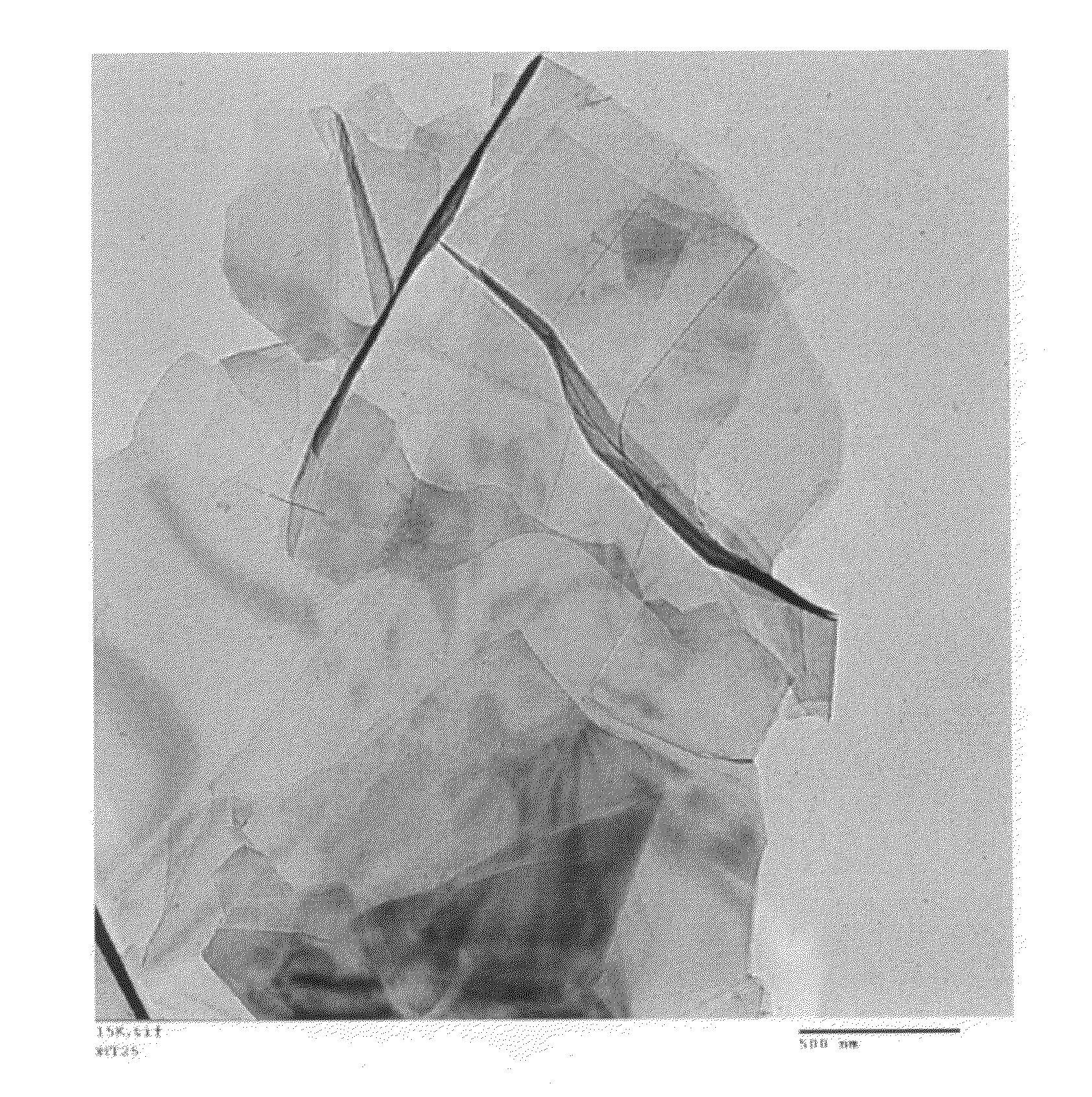
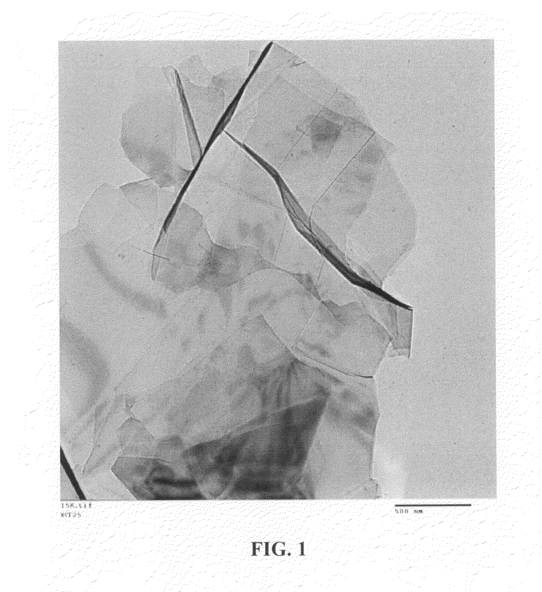
[0078]Continuous graphite fiber yarns (Magnamite from Hercules) were cut into segments of 5 mm long and then ball-milled for 48 hours. Approximately 20 grams of these milled fibers were immersed in a mixture of 2 L of formic acid and 0.1 L of hydrogen peroxide at 45° C. for 60 hours. Following the chemical oxidation intercalation treatment, the resulting intercalated fibers were washed with water and dried. The resulting product is a formic acid-intercalated graphite fiber material containing graphite oxide crystallites.

[0079]Subsequently, approximately ½ of the intercalated or oxidized fiber sample was transferred to a furnace pre-set at a temperature of 600° C. for 30 seconds. The compound was found to induce extremely rapid and high expansions of graphite crystallites. The as-exfoliated graphite fiber is designated as Sample-1a. Approximately half of Sample 1-a material was subjected to de-oxygenation at 1,100° C. for 20 minutes in a nitrogen a...

example 2

Graphene from Sulfuric Acid Intercalation and Exfoliation of MCMBS

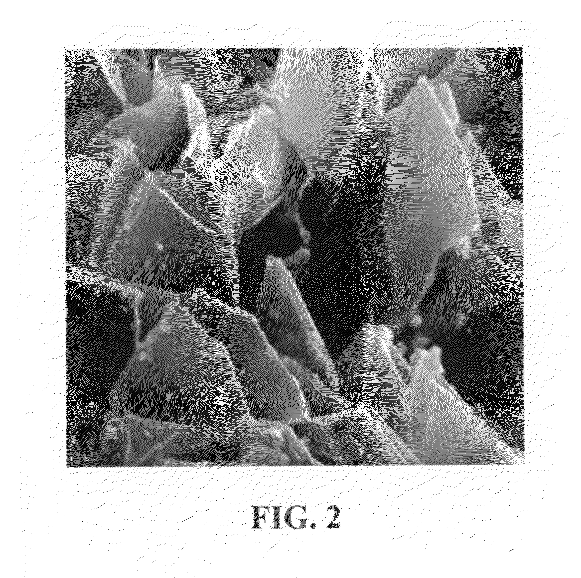
[0083]MCMB 2528 microbeads were supplied by Alumina Trading, which was the U.S. distributor for the supplier, Osaka Gas Chemical Company of Japan. This material has a density of about 2.24 g / cm3; a particle size maximum for at least 95% by weight of the particles of 37 microns; median size of about 22.5 microns and an inter-planar distance of about 0.336 nm. MCMB 2528 (10 grams) were intercalated with an acid solution (sulfuric acid, nitric acid, and potassium permanganate at a ratio of 4:1:0.05) for 30 minutes. Upon completion of the reaction, the mixture was poured into deionized water and filtered. The intercalated MCMBs were repeatedly washed in a 5% solution of HCl to remove most of the sulphate ions. The sample was then washed repeatedly with deionized water until the pH of the filtrate was neutral. The slurry was spray-dried and stored in a vacuum oven at 60° C. for 24 hours. The dried powder sample was placed ...

example 3

Oxidation, Exfoliation, and De-Oxygenation of Natural Graphite

[0085]Graphite oxide was prepared by oxidation of natural flake graphite with sulfuric acid, sodium nitrate, and potassium permanganate at a ratio of 4:1:0.05 at 30° C. for 24 hours, according to the method of Hummers [U.S. Pat. No. 2,798,878, Jul. 9, 1957]. Upon completion of the reaction, the mixture was poured into deionized water and filtered. The sample was then washed with 5% HCl solution to remove most of the sulfate ions and residual salt and then repeatedly rinsed with deionized water until the pH of the filtrate was approximately 7. The intent was to remove all sulfuric and nitric acid residue out of graphite interstices. The slurry was spray-dried and stored in a vacuum oven at 60° C. for 24 hours. The interlayer spacing of the resulting laminar graphite oxide was determined by the Debey-Scherrer X-ray technique to be approximately 0.73 nm (7.3 Å), indicating that graphite has been converted into graphite oxide...


PUM

PropertyMeasurementUnit
thicknessaaaaaaaaaa
heightaaaaaaaaaa
heightaaaaaaaaaa

Abstract

A surface-modified nano graphene platelet (NGP), comprising: (a) a nano graphene platelet having a thickness smaller than 10 nm; and (b) discrete, non-continuous, and non-metallic bumps or nodules bonded to a surface of the graphene platelet to serve as a spacer. When multiple surface-modified NGP sheets are stacked together to form an electrode, large numbers of electrolyte-accessible pores are formed, enabling the formation of large amounts of double layer charges in a supercapacitor, which exhibits an exceptionally high specific capacitance.

Description

[0001]This invention is based on the results of a research project sponsored by the US DOE SBIR Program. The US government has certain rights on this invention.FIELD OF THE INVENTION[0002]The present invention relates generally to the field of supercapacitors or ultracapacitors, and more particularly to the nano graphene platelet-based electrode and supercapacitors containing such an electrode.BACKGROUND OF THE INVENTION[0003]Electrochemical capacitors (ECs), also known as ultracapacitors or supercapacitors, are being considered for uses in hybrid electric vehicles (EVs) where they can supplement a battery used in an electric car to provide bursts of power needed for rapid acceleration, the biggest technical hurdle to making battery-powered cars commercially viable. A battery would still be used for cruising, but capacitors (with their ability to release energy much more quickly than batteries) would kick in whenever the car needs to accelerate for merging, passing, emergency maneuv...

Claims


Application Information

Patent Timeline
Patent Type & Authority Applications(United States)
IPC IPC(8): H01G9/058C01B31/02C25B11/12B32B3/10
CPCB82Y30/00B82Y40/00C01B31/0469C01B31/0476C01B31/0484C01B2204/02Y10T428/24802C01B2204/32H01G11/36H01G11/46Y02E60/13H01G11/24C01B2204/04C01B32/19C01B32/192C01B32/194
Inventor ZHAMU, ARUNAYU, ZENNINGLIU, CHEN-GUANGJANG, BOR Z.
Owner NANOTEK INSTR GRP LLC
Why Eureka
Try Eureka