Eureka AIR delivers breakthrough ideas for toughest innovation challenges, trusted by R&D personnel around the world.

Coordination of HP and LP EGR

a technology of exhaust gas recirculation and motor vehicles, which is applied in the direction of electric control, machines/engines, mechanical equipment, etc., can solve the problemsaccelerating the ageing of engine components and associated exhaust systems, and reducing combustion and exhaust temperatures. , to achieve the effect of increasing nitrogen-oxide (nox) emissions, reducing oxygen content, and high combustion and exhaust temperatures

Active Publication Date: 2011-07-07
FORD GLOBAL TECH LLC
View PDF32 Cites 19 Cited by
  • Summary
  • Abstract
  • Description
  • Claims
  • Application Information

AI Technical Summary

Benefits of technology

[0002]A boosted engine may exhibit higher combustion and exhaust temperatures than a naturally aspirated engine of equivalent output power. Such higher temperatures may increase nitrogen-oxide (NOX) emissions and cause accelerated materials ageing in the engine and associated exhaust system. Exhaust-gas recirculation (EGR) is one approach for combating these effects. EGR strategies reduce the oxygen content of the intake air charge by diluting it with exhaust. When the diluted air-exhaust mixture is used in place of ordinary air to support combustion in the engine, lower combustion and exhaust temperatures result. EGR also improves fuel economy in gasoline engines by reducing throttling losses and heat rejection.
[0005]At higher engine loads and speeds, still other issues arise. Flowing exhaust through an LP EGR loop increases the overall flow rate through the compressor, which may cause an over-speed condition and reduced compressor efficiency. This condition, if excessive, could lead to compressor choke. Flowing exhaust through an LP EGR loop also increases the gas temperature at the compressor inlet, which, in turn, increases compressor outlet temperature. On the other hand, uncooled HP EGR at high loads may cause excessive MAT, reducing engine power and / or causing an excessive outflow of smoke from the engine. These conditions may also make the compressor prone to surge.
[0006]Other, quite different issues arise during transient conditions. LP EGR, while improving turbocharger efficiency at lower engine loads, takes longer to purge from the intake system. This is because the purge volume includes not only the intake manifold, but everything from the intake manifold to the inlet of the compressor. HP EGR, while more easily purged from the intake manifold, reduces mass flow through the turbine. This reduces turbocharger speed, which increases lag. Thus, both EGR strategies can potentially degrade the engine's ability to respond to load and speed transients.
[0007]Further issues arise during catalyst warm up—another transient condition. Being very well cooled, LP EGR does not enable exhaust temperatures as high as uncooled HP EGR. Thus, in some cases catalyst light-off may be unacceptably delayed when running LP EGR. Uncooled HP EGR, on the other hand, enables higher exhaust temperatures but provides significantly reduced mass flow through the exhaust system. This can reduce the thermal energy in the exhaust and may also reduce the heat transfer coefficient.
[0008]The inventors herein have recognized these issues and the interrelationships between them, and have devised a series of approaches to address them. Therefore, one embodiment of this disclosure provides a method for charging an intake manifold of an engine. The method comprises adjusting an LP EGR flow rate and an uncooled HP EGR flow rate within first limits to maintain a target dilution level in the intake manifold at steady-state. The method further comprises adjusting the LP EGR and uncooled HP EGR rates within second limits, different from the first, to maintain the target dilution level in the intake manifold during transient conditions. In this manner, HP and LP EGR may be controlled coordinately during steady state and transient conditions. By dynamically changing the values that bracket the HP and LP EGR flow rates depending on conditions, engine longevity, fuel economy, and emissions control can be improved while enabling rapid response to transients.

Problems solved by technology

Such higher temperatures may increase nitrogen-oxide (NOX) emissions and cause accelerated materials ageing in the engine and associated exhaust system.
When the diluted air-exhaust mixture is used in place of ordinary air to support combustion in the engine, lower combustion and exhaust temperatures result.
This can result in a number of issues.
First, high levels of intake-air dilution may cause poor combustion stability at lower engine loads, resulting in increased hydrocarbon (HC) and carbon-monoxide (CO) emissions.
Second, at high HP EGR flow rates, mass flow through the compressor is significantly reduced, making the compressor prone to surge.
In short, to achieve high MAT, exhaust may be routed through an uncooled HP EGR system, but that may cause surge.
To avoid surge, the exhaust may be routed through a well-cooled LP EGR system, but this will increase HC and CO emissions.
Meanwhile, supplementary or alternative use of cooled HP EGR may introduce further issues.
For example, excessive fouling of an EGR cooler can occur when cooled HP EGR flow rate is allowed to fall below a suitable level.
At higher engine loads and speeds, still other issues arise.
Flowing exhaust through an LP EGR loop increases the overall flow rate through the compressor, which may cause an over-speed condition and reduced compressor efficiency.
This condition, if excessive, could lead to compressor choke.
On the other hand, uncooled HP EGR at high loads may cause excessive MAT, reducing engine power and / or causing an excessive outflow of smoke from the engine.
These conditions may also make the compressor prone to surge.
Other, quite different issues arise during transient conditions.
This reduces turbocharger speed, which increases lag.
Thus, both EGR strategies can potentially degrade the engine's ability to respond to load and speed transients.
Further issues arise during catalyst warm up—another transient condition.
Being very well cooled, LP EGR does not enable exhaust temperatures as high as uncooled HP EGR.
Thus, in some cases catalyst light-off may be unacceptably delayed when running LP EGR.
This can reduce the thermal energy in the exhaust and may also reduce the heat transfer coefficient.

Method used


Image

  • Coordination of HP and LP EGR
  • Coordination of HP and LP EGR
  • Coordination of HP and LP EGR

Examples


Embodiment Construction

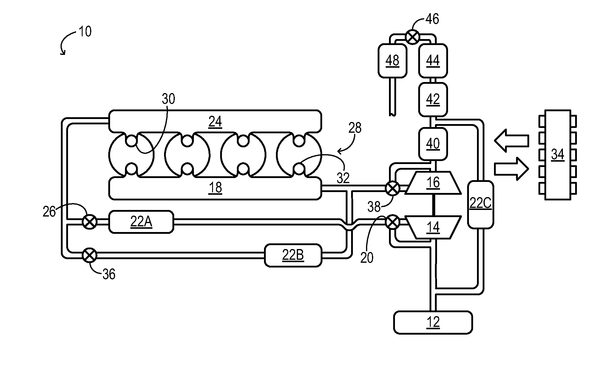
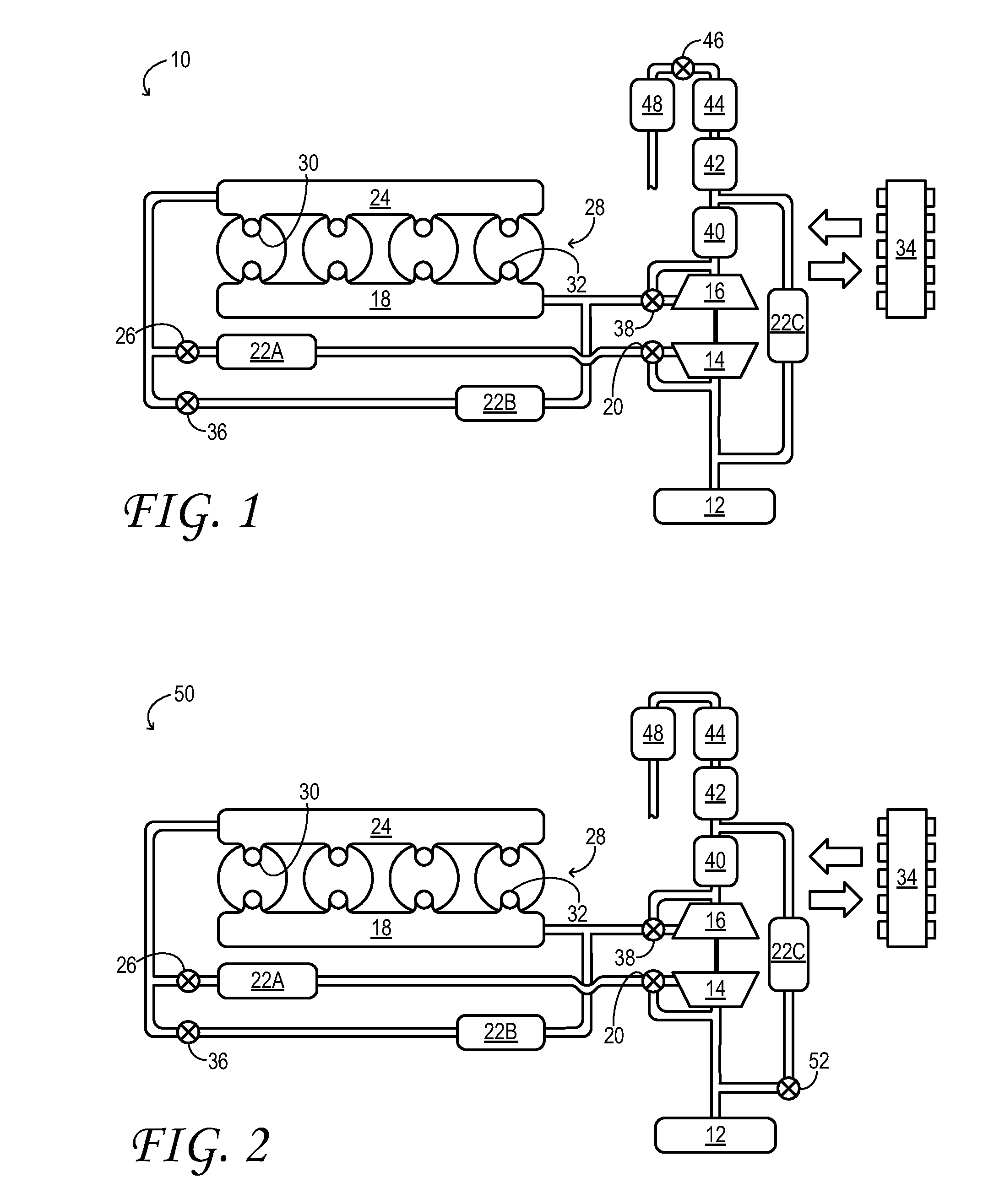
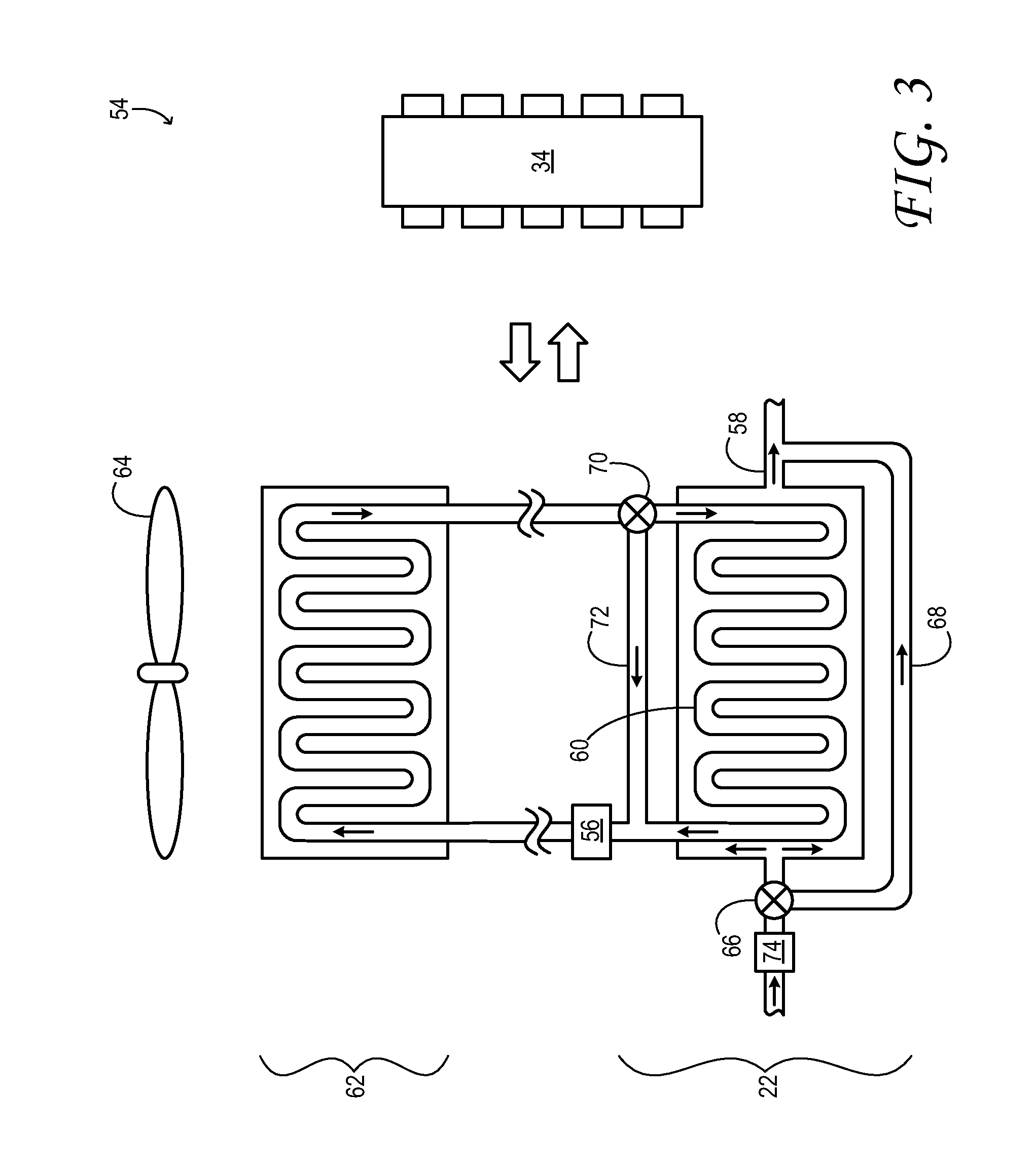
[0013]The subject matter of this disclosure is now described by way of example and with reference to the illustrated embodiments listed above. Components, process steps, and other elements that may be substantially the same in one or more embodiments are identified coordinately and are described with minimal repetition. It will be noted, however, that elements identified coordinately may also differ to some degree. It will be further noted that the drawing figures included in this disclosure are schematic and generally not drawn to scale. Rather, the various drawing scales, aspect ratios, and numbers of components shown in the figures may be purposely distorted to make certain features or relationships easier to see.

[0014]FIG. 1 schematically shows aspects of an example engine system 10 in one embodiment. In engine system 10, air cleaner 12 is coupled to the inlet of compressor 14. The air cleaner inducts fresh air from the ambient and provides filtered, fresh air to the compressor....


PUM


Abstract

A method for charging an intake manifold of an engine comprises adjusting an LP EGR flow rate and an uncooled HP EGR flow rate within first limits to maintain a target dilution level in the intake manifold at steady-state. The method further comprises adjusting the LP EGR and uncooled HP EGR rates within second limits, different from the first, to maintain the target dilution level in the intake manifold during transient conditions.

Description

TECHNICAL FIELD [0001]This application relates to the field of motor-vehicle engineering, and more particularly, to exhaust-gas recirculation (EGR) in motor-vehicle engine systems.BACKGROUND AND SUMMARY [0002]A boosted engine may exhibit higher combustion and exhaust temperatures than a naturally aspirated engine of equivalent output power. Such higher temperatures may increase nitrogen-oxide (NOX) emissions and cause accelerated materials ageing in the engine and associated exhaust system. Exhaust-gas recirculation (EGR) is one approach for combating these effects. EGR strategies reduce the oxygen content of the intake air charge by diluting it with exhaust. When the diluted air-exhaust mixture is used in place of ordinary air to support combustion in the engine, lower combustion and exhaust temperatures result. EGR also improves fuel economy in gasoline engines by reducing throttling losses and heat rejection.[0003]In a boosted engine system equipped with a turbocharger compressor...

Claims


Application Information

Patent Timeline
Patent Type & Authority Applications(United States)
IPC IPC(8): F02B47/08
CPCF02B47/08F02D41/005F02D41/0065F02M25/0707F02D41/0235F02M25/0722F02M25/0732Y02T10/47F02M25/0709F02M26/05F02M26/06F02M26/19F02M26/24Y02T10/40
Inventor STYLES, DANIEL JOSEPHDRONZKOWSKI, DAVID JOSEPHKURTZ, ERIC
Owner FORD GLOBAL TECH LLC
Why Eureka
Eureka Blog
Learn More