Eureka AIR delivers breakthrough ideas for toughest innovation challenges, trusted by R&D personnel around the world.

Electronic load simulator device for testing RF coils

Active Publication Date: 2011-07-07
KONINKLIJKE PHILIPS ELECTRONICS NV
View PDF6 Cites 4 Cited by
  • Summary
  • Abstract
  • Description
  • Claims
  • Application Information

AI Technical Summary

Benefits of technology

[0022]In case of image quality tests of a receiving coil, the usage of this controlled diode has the advantage, that during RF transmission for excitation of magnetic resonances the electric load induced by the active electrical component to the receiving coil can be changed or even turned off. In other words, during transmission of an RF signal for magnetic resonance excitation the active electrical component can be made transparent to the exciting RF field. This allows avoiding B1 distortions. For example, as diodes PIN diodes can be used which under zero or reverse bias have a low capacitance, such that electrical currents at the RF frequency used for excitation of the magnetic resonances are blocked. In contrast, in case the magnetic resonance machine is in data acquisition mode, wherein RF signals for example induced by free-induction decays originating from spins comprised in the phantoms are acquired, the circuit of the active electrical component switches the diode for allowing a current flow through the diode. For example, under a forward bias of 1 mA, a typical PIN diode will have an RF resistance of about 1 ohm making it a good RF conductor. In this case, during usage of the MR coil for acquiring RF images an electric load can be emulated to the MR coil by the electric circuit.
[0024]In accordance with a further embodiment of the invention, the electric circuit comprises a network of active and / or passive electrical components. The usage of a network of electrical components has the advantage that in a homogeneous manner over a large spatial area an electric load can be emulated by the electric circuit to the MR coil. Preferably, the coil testing arrangement is positioned in the field of view of the MR coil wherein the electric circuit is homogeneously circumscribing this field of view parallel to the surface area defined by the MR coil itself.
[0025]In accordance with a further embodiment of the invention, the network is formed on a printed circuit board and / or a conducting sheet material on a mechanical support. In the case of a printed circuit board, the advantage is an easy manufacturability. Any kinds of electrical components can be easily assembled on such a printed circuit board. One requirement which needs to be fulfilled for all kinds of electric circuits used in the coil testing arrangement is that the electric circuit does not comprise any magnetic components since these components would further distort magnetic fields in an unwanted manner.
[0027]In accordance with a further embodiment of the invention, the electric circuit comprises fixation points for fixing the electric circuit to MR coil unit and / or the phantom. The usage of such fixation points allows to spatially position the coil testing arrangement accurately with respect to the magnetic resonance receiving and / or transmitting coil and / or patient table and / or even the MR system itself. In this context, the term MR system is understood as the mechanical structure comprising a quadrature body coil or magnet covers or the MR magnet itself. Accurate positioning especially of the electric circuit allows for further improvement of the quality of the electric load which is emulated to the MR coil. The reason is that the electric load emulated to the MR coil does not only depend on the electric circuit itself but also on the relative spatial position of the electric circuit with respect to the MR coil.
[0028]In accordance with a further embodiment of the invention, the electric circuit further comprises a radio frequency transmission coil. The usage of an additional RF transmitting probe has the advantage, that further possibilities for characterization and diagnostics of RF receiver coils can be provided. For example, by means of such a radio frequency transmission coil, an RF signal as it would be generated by a free-induction decay can be simulated such that testing of the RF receiver coil can be performed without using any previous RF transmission for spin excitation purposes. In this way the electronic load would emulate not only the conductivity of human tissue but also its response to an MR excitation, enabling testing receiving RF coils for instance without using an external transmitting coil.

Problems solved by technology

Even though, such a phantom does not properly simulate human tissue, by the additional usage of the electrical circuit the magnetic resonance coil can nevertheless be electrically loaded in a desired manner.

Method used


Image

  • Electronic load simulator device for testing RF coils
  • Electronic load simulator device for testing RF coils
  • Electronic load simulator device for testing RF coils

Examples


Embodiment Construction

[0041]In the following, similar elements are depicted by the same reference numerals.

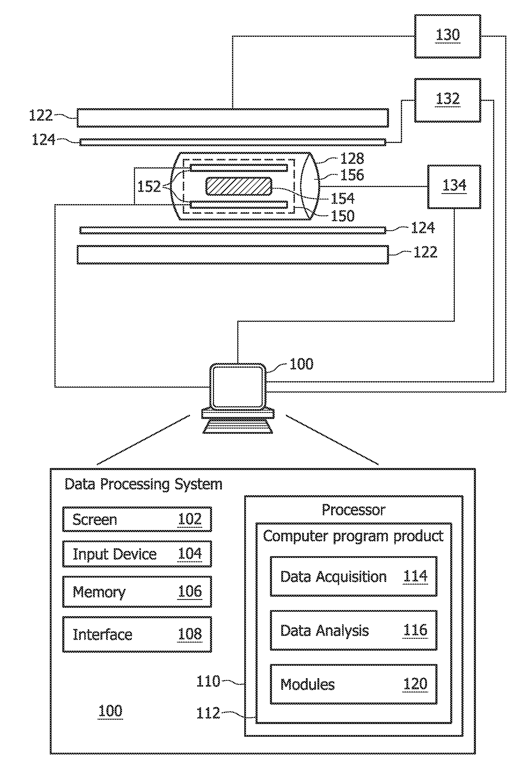
[0042]FIG. 1 is a schematic illustrating an MRI system according to the invention. Only major components over a preferred MRI system which incorporate the present invention are shown in FIG. 1. The magnetic resonance imaging apparatus comprises a data processing system 100, wherein the data processing system 100 typically comprises a computer screen 102 and an input device 104. Such an input device could be for example a keyboard or a mouse. The MRI system further comprises a memory 106 and an interface 108. The interface is adapted for communication and data exchange with typical hardware MRI components.

[0043]Typical hardware MRI components are for example a main field control unit 130 adapted for controlling the main field of the magnet 122. The interface 108 is also adapted to communicate with the gradient coil unit 132, wherein respective gradient coils 124 are preferably self-shielded gradient ...


PUM


Abstract

The invention relates to a magnetic resonance coil testing arrangement (150) comprising an electric circuit (152; 302) for emulating an electrical load to a magnetic resonance coil, wherein the electric circuit (152; 302) is adapted for emulating an electrical load corresponding to an electrical load induced by organic tissue at the magnetic resonance frequency of the magnetic resonance coil.

Description

TECHNICAL FIELD[0001]The invention relates to a magnetic resonance coil testing arrangement, a method of testing a magnetic resonance system and a computer program product.BACKGROUND AND RELATED ART[0002]Magnetic resonance imaging (MRI) is a state of the art imaging technology which allows cross-sectional viewing of objects like the human body with unprecedented tissue contrast. MRI is based on the principles of nuclear magnetic resonance (NMR), a spectroscopic technique used by scientists to obtain microscopic chemical and physical information about molecules. The basis of both NMR and MRI is the fact, that atomic nuclei with non-zero spin have a magnetic moment. In medical imaging, usually nuclei of hydrogen atoms are studied since they are present in the body in high concentrations like for example water. The nuclear spin of elementary particles can resonate at a resonance frequency, if a strong DC magnetic field is applied. This magnetic resonance (MR) frequency is determined by...

Claims


Application Information

Patent Timeline
IPC IPC(8): G01R31/06
CPCG01R33/58G01R33/3642
Inventor POSSANZINI, CECILIAVRINTEN, MARINUS LUDOVICUS ADRIANUSBOUTELJE, MARCO
Owner KONINKLIJKE PHILIPS ELECTRONICS NV
Why Eureka
Eureka Blog
Learn More