Unfortunately, these materials deliver relatively capacities.
Therefore, using a high capacity active material on one
electrode but not another has a limited effect.
Separately, many conventional lithium
ion cell electrode active materials suffer from substantial irreversible capacity losses, which indicate that some active material either degrades or is not used.
Similarly, the negative
electrode material may be said to undergo “activation.” Initial
cycling may involve substantial capacity losses due to SEI layer formation, changes in morphological structures, and other reasons.
Some losses result in fewer lithium ions available for
cycling, e.g., when lithium is consumed during SEI layer formation.
For example, a
cell may operate at conditions where the active portion of the positive electrode is not completely used during
cycling prior to activation because some lithium ions have been irreversibly trapped in the negative electrode (due to, e.g., SEI layer formation) and not available for cycling.
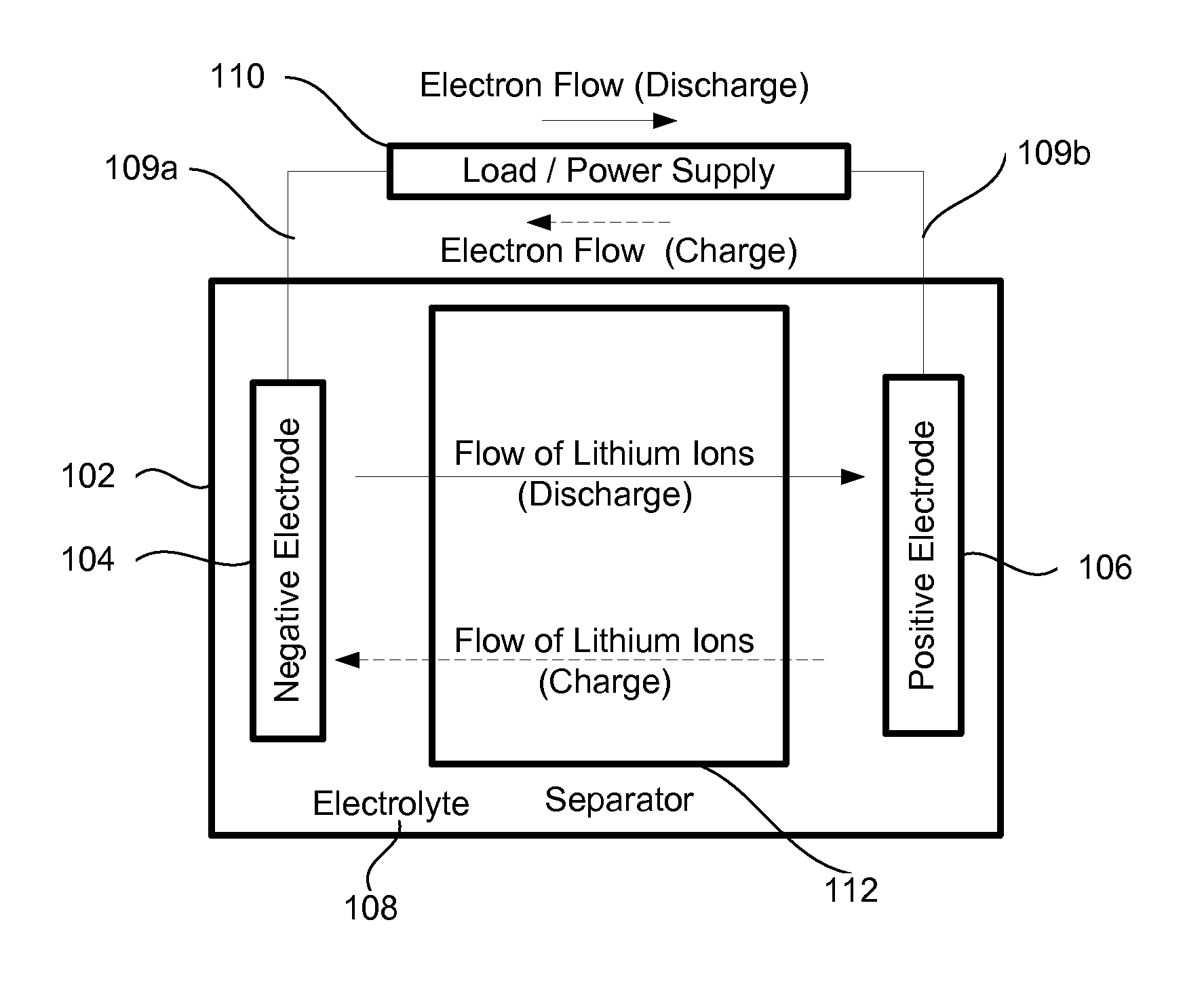
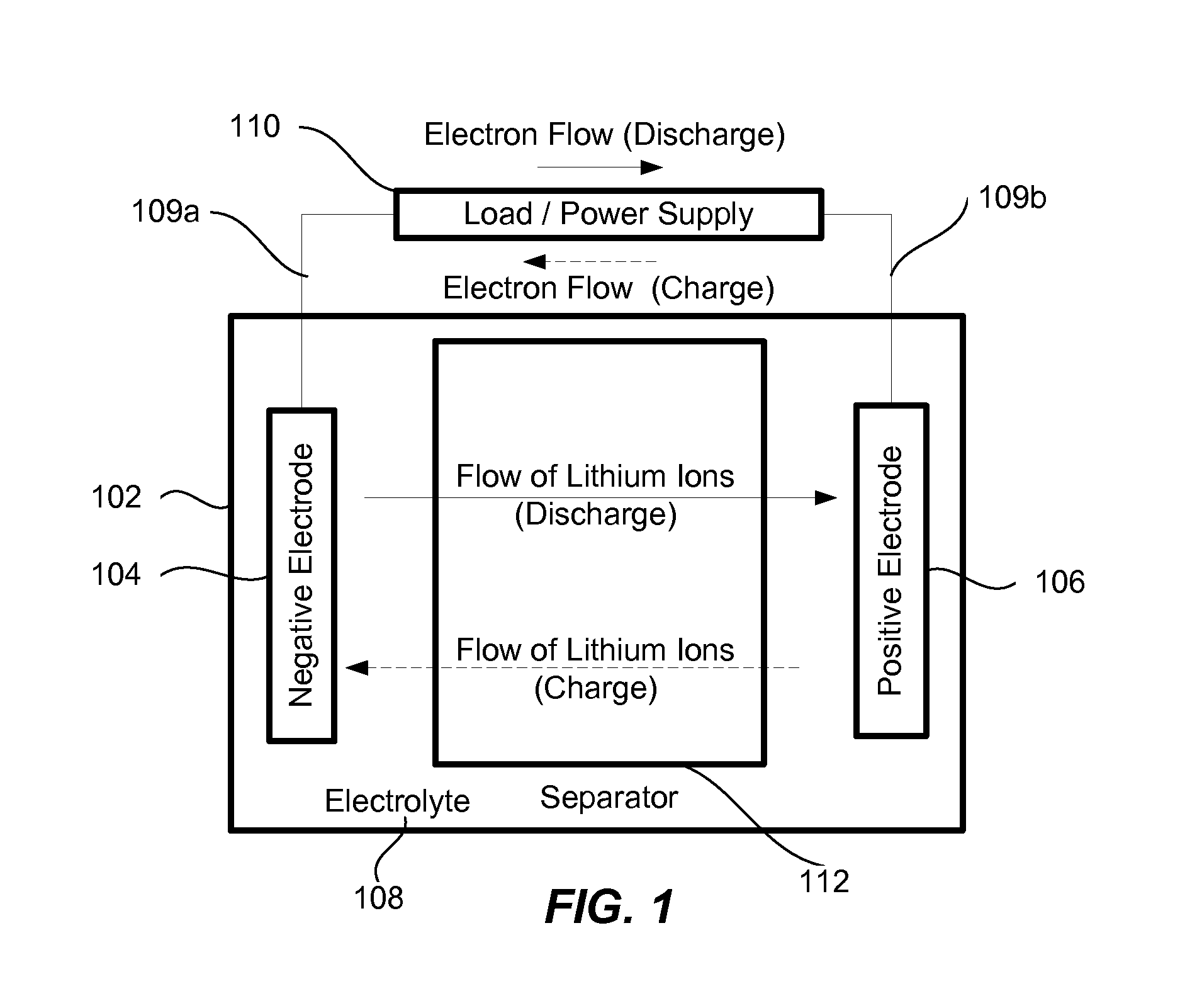
Generally, it is not desirable to transfer more lithium ions that can be inserted into the negative active material for safety reasons (e.g., to prevent lithium dendrites formation that can cause internal short).
Cell's theoretical capacity may be limited by a number of factors including characteristics of the positive and negative electrodes and the number of ions available for cycling.
For example, even when both electrodes have substantial
insertion capacities, there may be not enough ions available in the
cell to transfer between them and make use of the available
insertion capacities.
However, in other situations, the theoretical capacity may be limited by other factors, such as the
insertion capacity of one or more electrodes.
As a result, some fraction of the available transferable ions can not be utilized (and is not transferred, as a result) and do not
impact the theoretical capacity.
A theoretical capacity may be also limited by the insertion capacities of the two electrodes determined by a number of insertion sites available on the electrodes.
This irreversible
trapping causes some capacity losses as evidenced by low Coulombic efficiencies during formation.
Both positive and negative electrodes may have an excess of insertion sites, but there is not enough transferable ions to be inserted in these sites.
The theoretical capacity is therefore limited by one or more of the insertion capacities.
It has been found that conventional
graphite electrodes are very susceptible, for example, to dissolved
manganese ions and rapidly degrade when combined with the composite active materials containing
manganese.
As mentioned, such irreversible capacity losses may be caused by, e.g., SEI layer formation.
High surface area negative electrodes, such as
nanowire negative electrodes, may result in particularly large lithium losses.
Further, low electrical
conductivity and large
volume change of many high capacity negative active materials (e.g.,
silicon) may lead to residual lithium remaining on the negative electrode even during deep discharges.
Often such transformation corresponds to some capacity loses.
The negative active material used to store this excess of transferable ions remains “unused” or “wasted” from the capacity perspective, since the ions stored in it are not transferred and do not contribute to the theoretical capacity.
Such lithium may be trapped without effecting negative insertion capacity.
As a result, an SEI layer forming on the layer with nanowires will irreversibly trap substantially more lithium.
The overall
cell voltage 306 (i.e., the difference between the positive electrode
voltage and the negative electrode
voltage) rapidly decreases as the cell approaches the complete
discharge state and, at some point, operating as such a
low voltage becomes impractical.
It is believed that these changes negatively
impact overall cell performance by degrading negative active materials (e.g., worsening electrical
conductivity).
As a result, less active material is used per
cell volume leading to a lower overall cell capacity.
Moreover, the coated plates may be pre-heated to between about 60 and 120 degrees Centigrade making the active material layer more susceptible to uniform compression.
Moreover, the pressure may not be even within different parts of the cells and the corners of the prismatic cell may be left empty.
Empty pockets may not be desirable within the lithium ions cells because electrodes tend to be unevenly pushed into these pockets during electrode swelling.
However, such cell typically requires multiple sets of positive and negative electrodes and a more complicated alignment of the electrodes.

