Phase contrast imaging and preparing a tem therefor

a phase contrast and imaging technology, applied in the field of transmission electron microscopes, can solve the problems of difficult alignment on standard tems, difficult fabrication and installation, and difficulty in accurately forming a hole or electrode system a few hundred nanometers in lateral dimensions, and achieves the effect of simple phase plate positioning and easy placemen

Active Publication Date: 2011-07-21
JEOL LTD
View PDF10 Cites 25 Cited by
  • Summary
  • Abstract
  • Description
  • Claims
  • Application Information

AI Technical Summary

Benefits of technology

[0014]Applicants have discovered that Zernike-like phase contrast imaging is achieved by the charging of a suitable hole-free thin film by the incident electron beam itself to produce a suitable phase plate, and has further discovered that a strong primary electron beam can be used to fabricate the through bore in a hole-free thin film in situ to form a standard Zernike phase plate (ZPP). These discoveries permit phase contrast imaging requiring substantially no alignment, as no hole is provided and as the charging is naturally localized near the center of the phase plate in the former case, and in the latter case, substantially no alignment is needed because the hole is bored in situ and the center of the beam is the same for the boring as it is for imaging at conditions identical or similar to the imaging conditions. In both cases the electron beam itself is used to prepare the hole-free thin film for imaging. As both of these techniques obviate the need for precision positioning equipment and sophisticated fabrication of ZPP hardware, the present invention enables simplified phase plate positioning in any plane of the TEM conjugated with the back focal plane (BFP). The use of the electron beam itself to prepare the phase plate for imaging either by hole drilling or by charging, removes the limitations of pre-fabricating a ZPP. The in situ fabricated ZPP has the appropriate hole size for ZPP imaging because the ZPP is prepared by the beam itself during the hole boring. The simplified phase plate hardware (the hole-free thin film) can be easily placed within the objective lens polepiece gap, for example directly in one of the standard holes of the objective aperture strip in a standard TEM.

Problems solved by technology

There are several problems with ZPPs that have been previously viewed as separate issues.
ZPPs require a precise hole in a carbon film or a Boersch lens or einzel lens to be fabricated at the ZPP centre; then they are very difficult to align precisely on standard TEMs; and, in operation, can suffer defects due to “charging”.
Due to the strict fabrication and positioning requirements they can also be expensive to manufacture and install.
Fabrication of a precise hole or electrode system a few hundred nanometers in lateral dimensions is generally challenging, and is typically performed with a focused ion beam or using micro-electro-mechanical fabrication methods.
Both of these are expensive, as they require expensive equipment, and typically require multiple fabrication steps.
Supporting these electrodes in alignment about a central axis with small borehole while ensuring adequate electrical isolation, and good mechanical support with a structure that minimizes interference with the electron beam in use, is challenging.
Unfortunately FIBs can lead to contamination of the device and damage by gallium ions.
Once produced, it is equally or more challenging to install the ZPP within the TEM, such that the hole is centered within the TEM so that in operation the unscattered beam passes through the hole.
Unfortunately, in standard TEMs, the back focal plane of the objective lens is located in the polepiece gap, which is not wide.
This is makes it all the more difficult to align and limits the ZPP hardware that can be used for positioning with respect to the electron beam.
Unfortunately there are significant cost disadvantages to including the additional transfer lens, and this generally requires custom built designs, increasing dimensions of the TEM, and further substantially precludes enabling existing TEMs from using phase contrast imaging by retrofit.
The transfer lens also leads to compromises in microscope performance in modes of operation other than Zernike phase plate imaging.
Once assembled and centered, ZPPs have known problems with respect to “charging”.

Method used


Image

  • Phase contrast imaging and preparing a tem therefor
  • Phase contrast imaging and preparing a tem therefor
  • Phase contrast imaging and preparing a tem therefor

Examples


Embodiment Construction

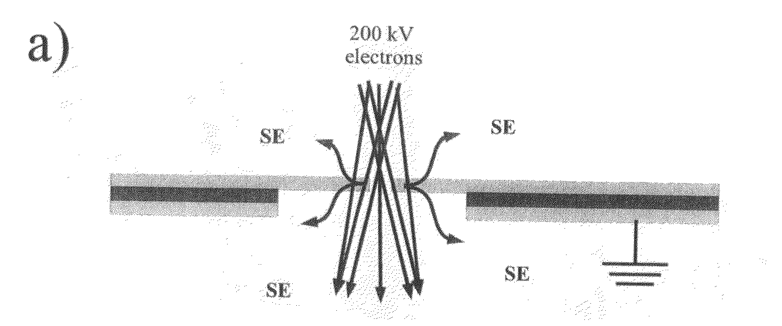
[0030]A technique is provided for phase contrast imaging involving preparing a hole-free thin film for TEM imaging with the electron beam itself focused on a center of the charged beam, which now does not have to be precisely aligned. The preparation involves charging the hole-free thin film, or boring a hole therethrough to produce a conventional ZPP, that is uncharacteristically centered within the TEM without equipment required for submicron alignment.

Charging of Hole-Free Thin Films

[0031]Several experiments were performed that demonstrate that a hole-free thin film in use is subject to charging that can produce a phase contrast transfer function (CTF) suitable for phase contrast imaging. Because only the difference between the phase shift experienced by the scattered beam with respect to the incident beam results in phase contrast, the uniform films without a hole were not expected to result in a phase contrast. It is a surprising and counterintuitive result that phase contrast ...


PUM


Abstract

New methods for phase contrast imaging in transmission electron microscopy use the imaging electron beam itself to prepare a hole-free thin film for use as an effective phase plate, in some cases eliminating the need for ex-situ fabrication of a hole and reducing requirements for the precision of the ZPP hardware. The electron optical properties of the ZPP hardware are modified primarily in two ways: by boring a hole using the electron beam; and/or by modifying the electro-optical properties by charging induced by the primary beam. Furthermore a method where the sample is focused by a lens downstream from the ZPP hardware is disclosed. A method for transferring a back focal plane of the objective lens to a selected area aperture plane and any plane conjugated with the back focal plane of the objective lens is also provided.

Description

CROSS REFERENCE TO RELATED APPLICATIONS[0001]This instant application claims the benefit of prior U.S. Provisional Application Ser. No. 61 / 336,256 filed on Jan. 19, 2010.FIELD OF THE INVENTION[0002]The invention relates in general to the field of transmission electron microscopy, and in particular, to preparing a transmission electron microscope (TEM) for phase contrast imaging of phase objects using a hole-free thin film in a way that facilitates the manufacturing, and alignment of a phase plate.BACKGROUND OF THE INVENTION[0003]Zernike phase contrast imaging in a TEM increases contrast of phase objects in comparison to traditional (bright field) phase imaging, leading to decreased electron irradiation dose for a desired signal-to-noise ratio. Many samples of practical interest in TEM are sensitive to electron beam irradiation because their nature changes with increasing incident electron dose, and care must be taken to avoid artefacts [2-4]. The radiation damage is of serious conce...

Claims


Application Information

Patent Timeline
Patent Type & Authority Applications(United States)
IPC IPC(8): H01J37/26
CPCH01J37/04H01J37/26H01J2237/2614B82Y35/00H01J37/295
Inventor MALAC, MAREKBELEGGIA, MARCOKAWASAKI, MASAHIROEGERTON, RAY
Owner JEOL LTD
Why Eureka
Try Eureka