Integrated, Predictive, Radiance Sensor Apparatus and Method

Inactive Publication Date: 2011-07-21
UTAH STATE UNIVERSITY
View PDF0 Cites 20 Cited by
  • Summary
  • Abstract
  • Description
  • Claims
  • Application Information

AI Technical Summary

Benefits of technology

[0031]The system may thus provide correction data effective to correct the nominal output of a sensor to represent the actual radiance from a target, based on detect...

Problems solved by technology

The problem of interest is a sensor at one location viewing one or more targe...

Method used


Image

  • Integrated, Predictive, Radiance Sensor Apparatus and Method
  • Integrated, Predictive, Radiance Sensor Apparatus and Method
  • Integrated, Predictive, Radiance Sensor Apparatus and Method

Examples


example i

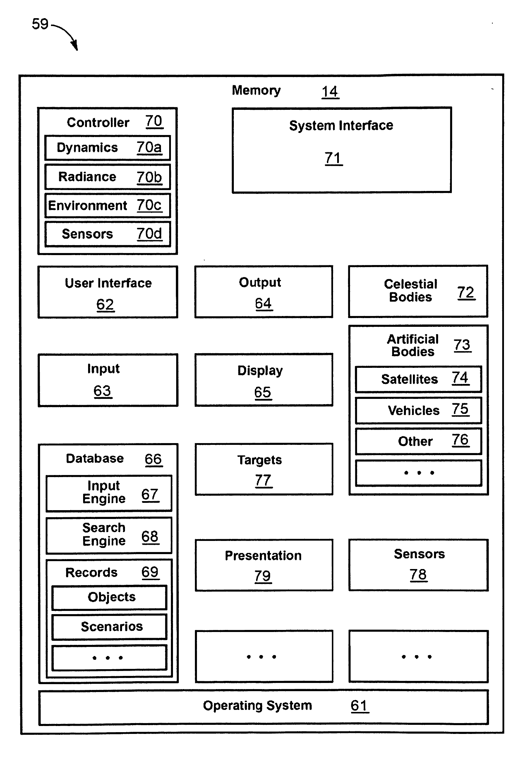
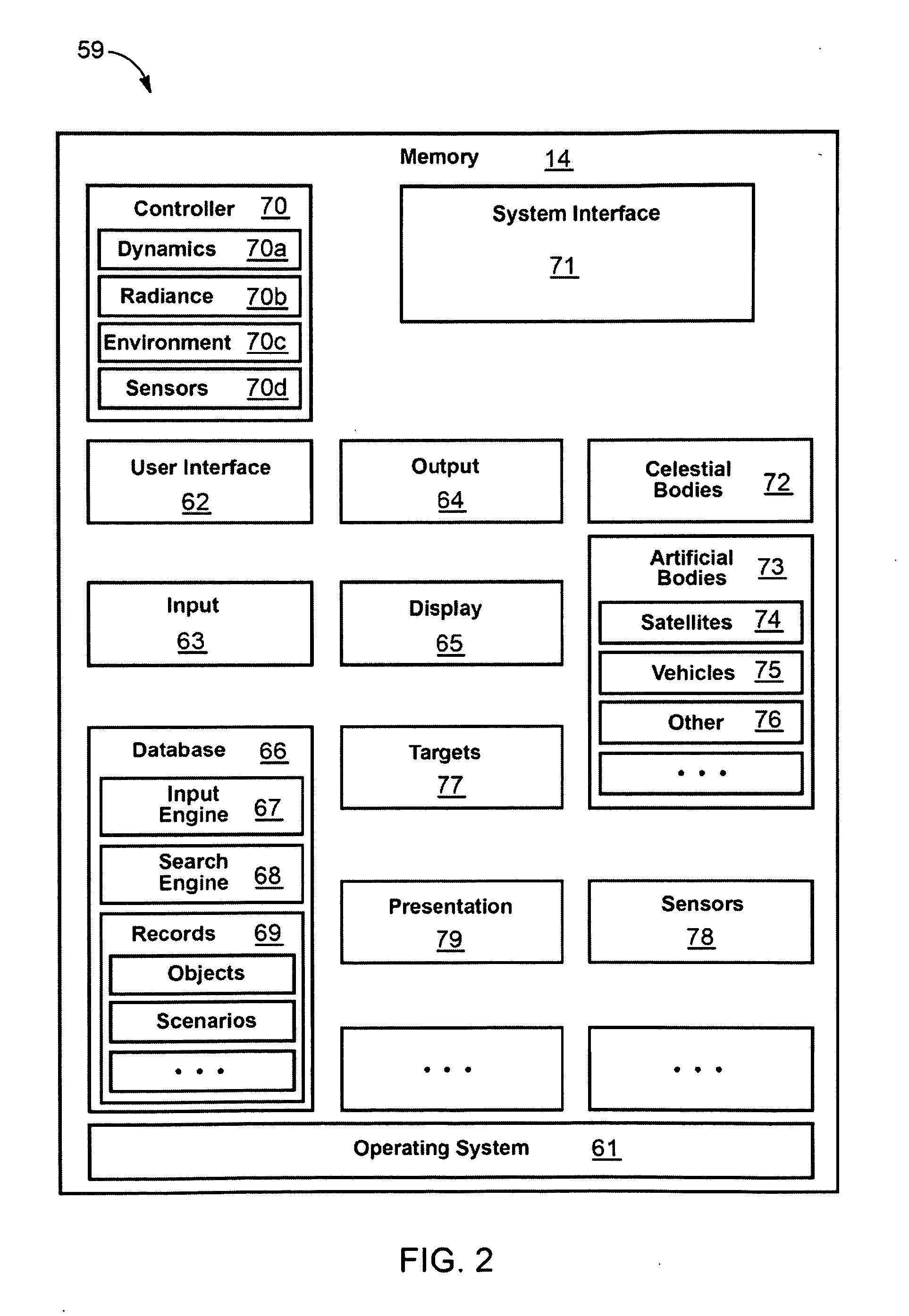
[0175]In selected embodiments, a user interface module (e.g., GUI) provides to a user or operator control to direct the simulation by setting simulation states and parametric values and to observe the results of the simulation. Time may be a primary parameter of the simulation. Simulation results may be computed at a specific time value. Internal to the simulation, time may be maintained relative to a specific time base (e.g., J2000 time).

[0176]A control module may sequence the execution of a single simulation “time frame” (at the current value of time) in a deterministic order based on the selected objects in the universe of simulation and physical causality. The control module may also manage the progression of time from one simulation frame to the next. Time may either increment by a specified step parameter (e.g., 0.1 second) or decrement by the specified step from one simulation time frame to the next. A new simulation time frame may then be computed at this new time. Time may ...

example ii

[0177]Spatial coordinates of all objects in the simulated universe may be maintained relative to a specific spatial coordinate base (e.g., such as Earth Centered Ecliptic with units of kilometers). The universe being simulated may contain representations of the objects being simulated, both natural and artificial (i.e., manmade). The operator may select via the interface module from an enumeration of objects to be included for purposes of the simulation.

[0178]Natural objects may include, but are not limited to, any body whose location and motion can be described mathematically and many are preprogrammed already, such as the sun, planets, moons, asteroids, comets, zodiacal light, stars, Milky Way galaxy, and the like. Man-made objects may include, but are not limited to, artificial satellites, missiles, ground vehicles, airborne vehicles, marine vehicles, aircraft, and the like. Satellites may be specified to be orbiting a particular parent body. Missiles may be in powered flight rel...

example iii

[0184]With respect to temperature, an object may compute the temperature of its surface elements at the given time. The temperatures may be a function of surface characteristics of the object, internal heat sources in the object (e.g., electronic equipment or motors), environmental heat loading (e.g., sunlight impinging on the object), and the like. Spectral radiance may be the multi-valued data element fundamental to calculating radiative transfer and electro-magnetic sensor performance. It may include the electro-magnetic power density per unit of spectral interval across some range of the electro-magnetic spectrum (e.g., number of watts per square centimeter per steradian in every 0.1 micrometer interval from 0.3 to 28.0 micrometers).


PUM


Abstract

A method of predicting sensor performance, such as focal plane array (FPA) behind optics casting an image based on radiant energy received from a target such as a star, planet, other celestial body, event, mass, artificial body, or the like. A user may select artificial, natural, or both types of bodies, and a dynamics module provides relative motion trajectories in space. Radiance proceeding from a target toward a sensor is modified by effects of bodies and the environment, considering any arbitrary selection of bodies and sensors, radiance effects, and relative motions therebetween, whether terrestrial or intergalactic in scale, location, or observation point. Thus, corrections and calibrations may improve images, factoring out cluttering effects of the environment and other bodies.

Description

RELATED APPLICATIONS[0001]This application claims the benefit of (1) co-pending U.S. Provisional Patent Application Ser. No. 61 / 026,424 filed on Feb. 5, 2008 and (2) co-pending U.S. Provisional Patent Application Ser. No. 61 / 148,136 filed on Jan. 29, 2009, both of which are incorporated herein by reference in their entirety.BACKGROUND[0002]1. The Field of the Invention[0003]This invention relates to computer systems applied to astrophysics imaging and modeling and, more particularly, to novel systems and methods for designing, testing, and evaluating sensor systems.[0004]2. Background[0005]The principles of physics describe the behaviors of objects in the universe. Objects may range from sub-atomic, atomic, or molecular particles to celestial bodies and galaxies. To the extent that observations have provided laws generally accepted, behaviors of various bodies may be described by suitable equations[0006]Meanwhile, the equations that characterize physical objects and their behavior m...

Claims


Application Information

Patent Timeline
IPC IPC(8): G06F19/00G06G7/48G06F17/50
CPCG06F17/50G06F30/00
Inventor ANDERSON, ROBERT
Owner UTAH STATE UNIVERSITY
Why Eureka
Try Eureka