
Isolation chamber and method of using the isolation chamber to make solar cell material

Inactive Publication Date: 2011-08-04
XUNLIGHT CORPORATION
View PDF1 Cites 17 Cited by
  • Summary
  • Abstract
  • Description
  • Claims
  • Application Information

AI Technical Summary

Benefits of technology

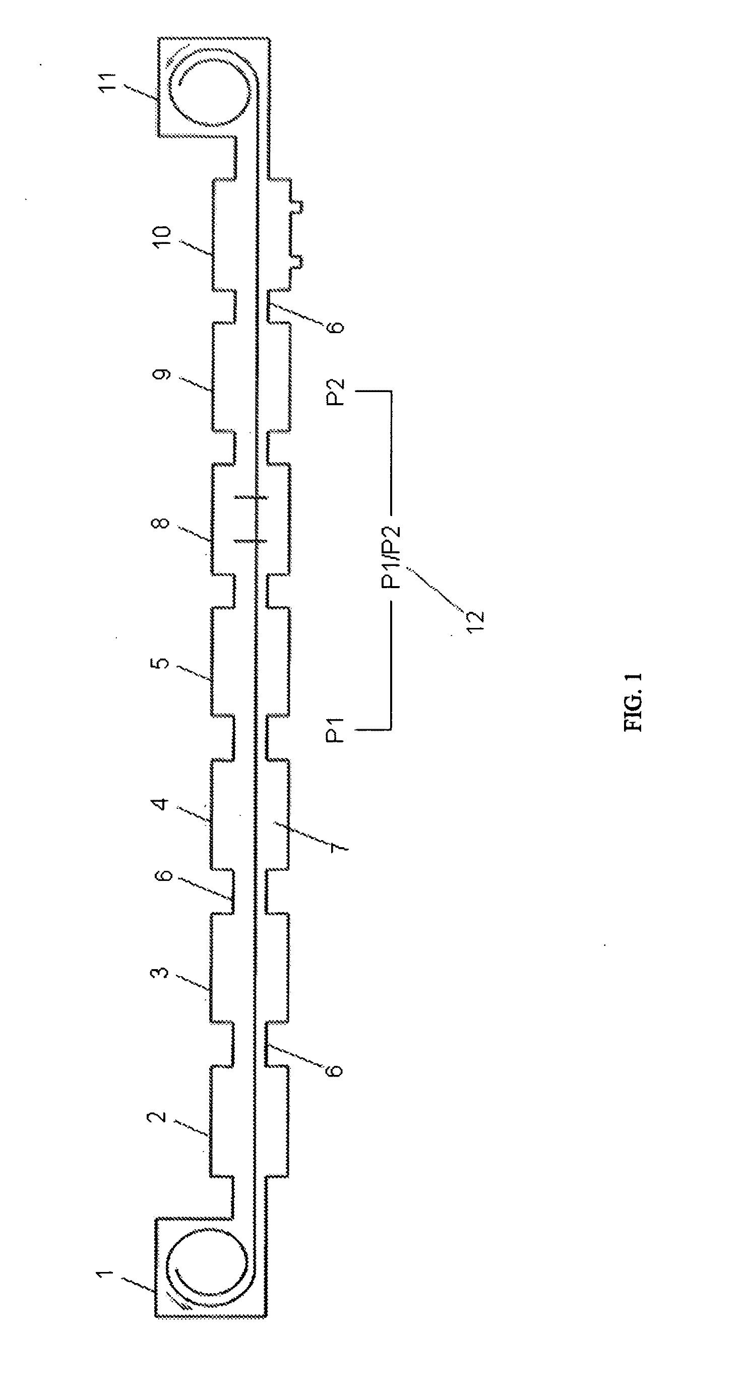
[0010]There is a need in the industry for an in-line continuous solar cell formation apparatus and process where the semiconductor material can be applied to a substrate and a transparent conductive oxide or other component can be applied to the semiconductor material in one continuous in-line process. To achieve such an in-line process it will be necessary to effectively isolate the varying environmental conditions in the deposition zones used to form the solar cell material. In addition, it will be necessary to accommodate significant pressure differentials in the various deposition zones to effectively eliminate cross contamination by the reactive components utilized in the deposition zones. As is known in the art, the reactive components used in the back reflector deposition zone, the semiconductor deposition zone and the transparent conductive oxide deposition zone are not compatible and any contamination of components between the deposition zones can significantly decrease the quality of the finished solar cell material. There is a need for an isolation chamber that can effectively eliminate cross contamination between deposition zones used in an in-line continuous solar cell material fabrication process. Such an isolation chamber will need to effectively separate deposition zones that have significantly different environmental conditions.

Problems solved by technology

The formation of such in-line continuous solar cell formation has been limited due to the vastly different environmental conditions present in the various deposition zones that are used to form the solar cell material.
The use of multiple processing lines to form the solar material greatly increases the cost of production of the solar cell material.
In addition, the additional, handling of the solar cell material can result in the creation of defects that significantly reduce the efficiency of the finished solar cell material.

Method used


Image

  • Isolation chamber and method of using the isolation chamber to make solar cell material
  • Isolation chamber and method of using the isolation chamber to make solar cell material
  • Isolation chamber and method of using the isolation chamber to make solar cell material

Examples


example 1

[0069]FIG. 6 illustrates a DPIU 500 comprising an evacuation space 503 in fluid communication with a first PIU 501 and a second PIU 502. One port of the first PIU 501 is connected to a first deposition space 507 while a second port of PIU 501 is connected to the evacuation space 503. One port of the second PIU 502 is connected to a second deposition space 508 and a second port of PIU 502 is connected to the evacuation space 503. The pressure in the first deposition space 507 proximate the first PIU 501 is ‘PI’. The pressure in the second deposition space 508 proximate the second PIU 502 is ‘P4’. The pressure in the evacuation space 503 proximate the first PIU 501 is ‘P2’. The pressure in the evacuation space 403 proximate the second PIU 502 is ‘P3’. A first sweep gas (e.g., H2) is provided into the first PIU 501 via inlet port 505. A second sweep gas (e.g., Ar) is admitted into the second PIU 502 via inlet port 506. The first and second sweep gases are removed from the evacuation sp...

example 2

[0070]A plurality or roll-to-roll deposition systems may be used to form the photovoltaic cell of FIG. 7. A large-scale thin-film silicon solar cell production line in the front-end facility comprises one roll-to-roll washing machine (not shown), one back reflector roll-to-roll production machine (FIG. 8) and one PECVD / ITO roll-to-roll production machine (FIG. 9). Stainless steel (SS) coils are used as substrates, which in some embodiments may have a thickness of 0.005″ (0.127 mm), a minimum width of 10″, a preferable width of 36″, and a minimum length of 5000 ft.

[0071]In the roll-to-roll washing machine, a roll of an uncleaned SS web substrate loaded at pay-off (wind-off) chamber is guided in a roll-to-roll wet chemical cleaning process through a detergent tank, a DI water rinse tank, a blower and dry station. An oil-free, particle-free, clean SS substrate web is then wound up together with protective interleaf onto a core at the take-up (windup) chamber of the washing machine.

[007...

example 3

[0074]With reference to FIG. 10, a vacuum roll-to-roll thin-film production machine may be used to form the photovoltaic cell of FIG. 7. The roll-to-roll production machine, illustrated in two sections to fit on the page, may be a single, continuous, roll-to-roll system. A large-scale thin-film silicon solar cell roll-to-roll production machine in the front-end facility comprises a substrate payout chamber, a plasma cleaning chamber, a back-reflector sputtering deposition chamber, a thin film silicon PECVD deposition chamber, a transparent conductor deposition chamber, and a substrate take up chamber. A differential process isolation unit (DPIU) is disposed between the back-reflector deposition chamber and the PECVD chamber. A second DPIU is disposed between the PECVD chamber and the transparent conductor deposition chamber. Stainless steel (SS) coils are used as substrates, which have a thickness of about 0.005″ (0.127 mm), a minimum width of about 10″, a preferable width of about ...


PUM

PropertyMeasurementUnit
Lengthaaaaaaaaaa
Lengthaaaaaaaaaa
Pressureaaaaaaaaaa

Abstract

Apparatuses and methods are provided for the continuous formation of solar cell material including an isolation chamber that reduces cross contamination between adjacent formation zones that are at different pressures.

Description

CROSS REFERENCE TO RELATED APPLICATIONS[0001]This application claims the benefit of U.S. provisional patent application Ser. No. 61 / 337,485 filed Feb. 3, 2010.BACKGROUND OF THE INVENTION[0002]The present invention is directed to an isolation chamber that is used as part of an in-line continuous fabrication of photovoltaic solar cell devices. The formation of such in-line continuous solar cell formation has been limited due to the vastly different environmental conditions present in the various deposition zones that are used to form the solar cell material. Because of the varying environmental conditions in the deposition zones, most solar cell material is made on more than on process line where the individual components of the solar cell material are deposited separately. As an example, the semiconductor material for the solar cell is deposited on a substrate in one forming operation and the transparent conductive top layer is applied to the semiconductor material on a separate depo...

Claims


Application Information

Patent Timeline
IPC IPC(8): H01L31/18H01L21/02
CPCC23C14/086C23C14/562C23C14/564C23C14/568C23C16/24Y02E10/50C23C16/4409C23C16/4412C23C16/545H01L31/1884H01L31/206C23C16/4408Y02P70/50
Inventor CAO, XINMINMOHRING, BRADLEY S.
Owner XUNLIGHT CORPORATION
Learn More