Flux and solder material and method of making same

Active Publication Date: 2011-08-11
NORDSON CORP
View PDF21 Cites 8 Cited by
  • Summary
  • Abstract
  • Description
  • Claims
  • Application Information

AI Technical Summary

Benefits of technology

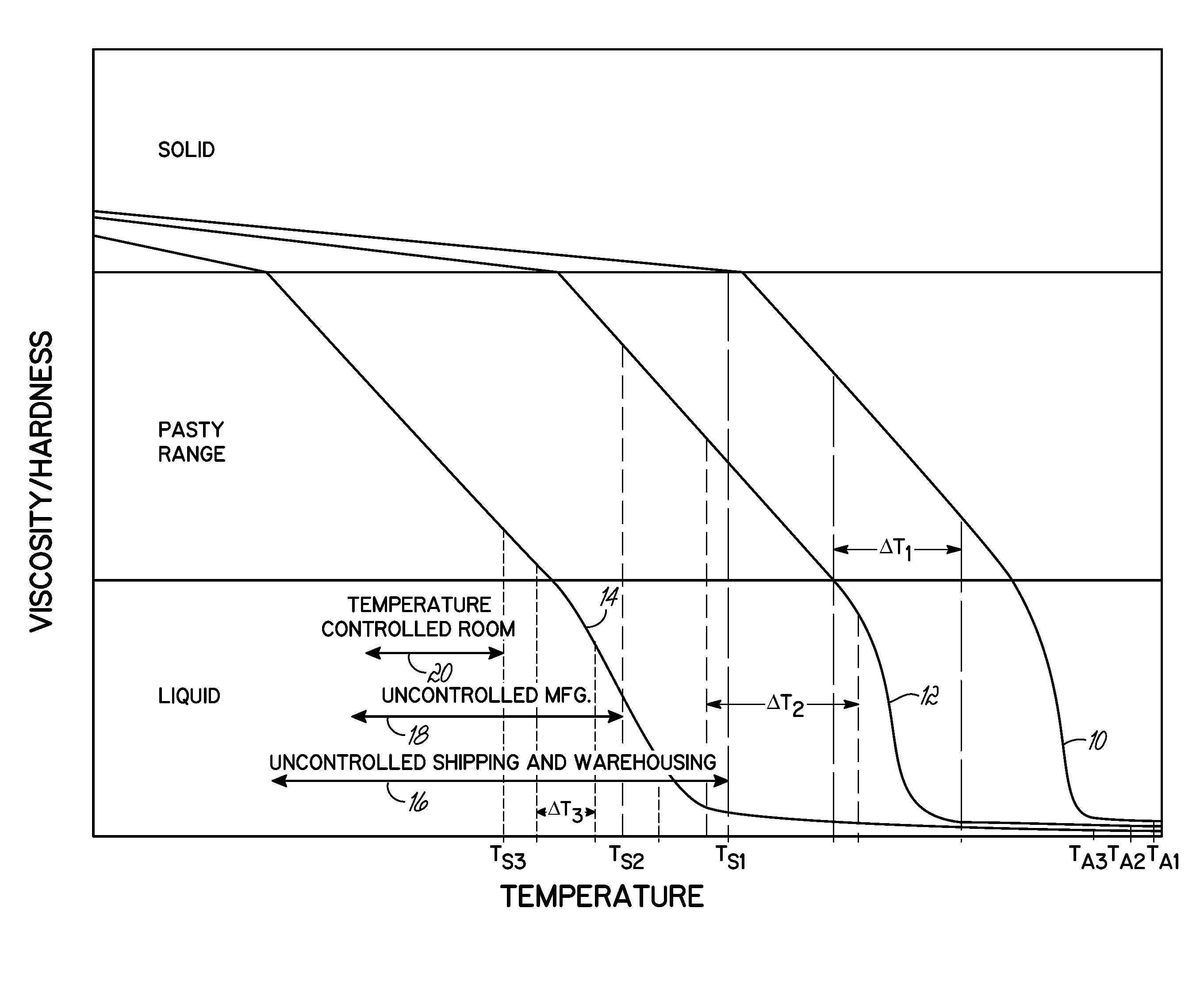
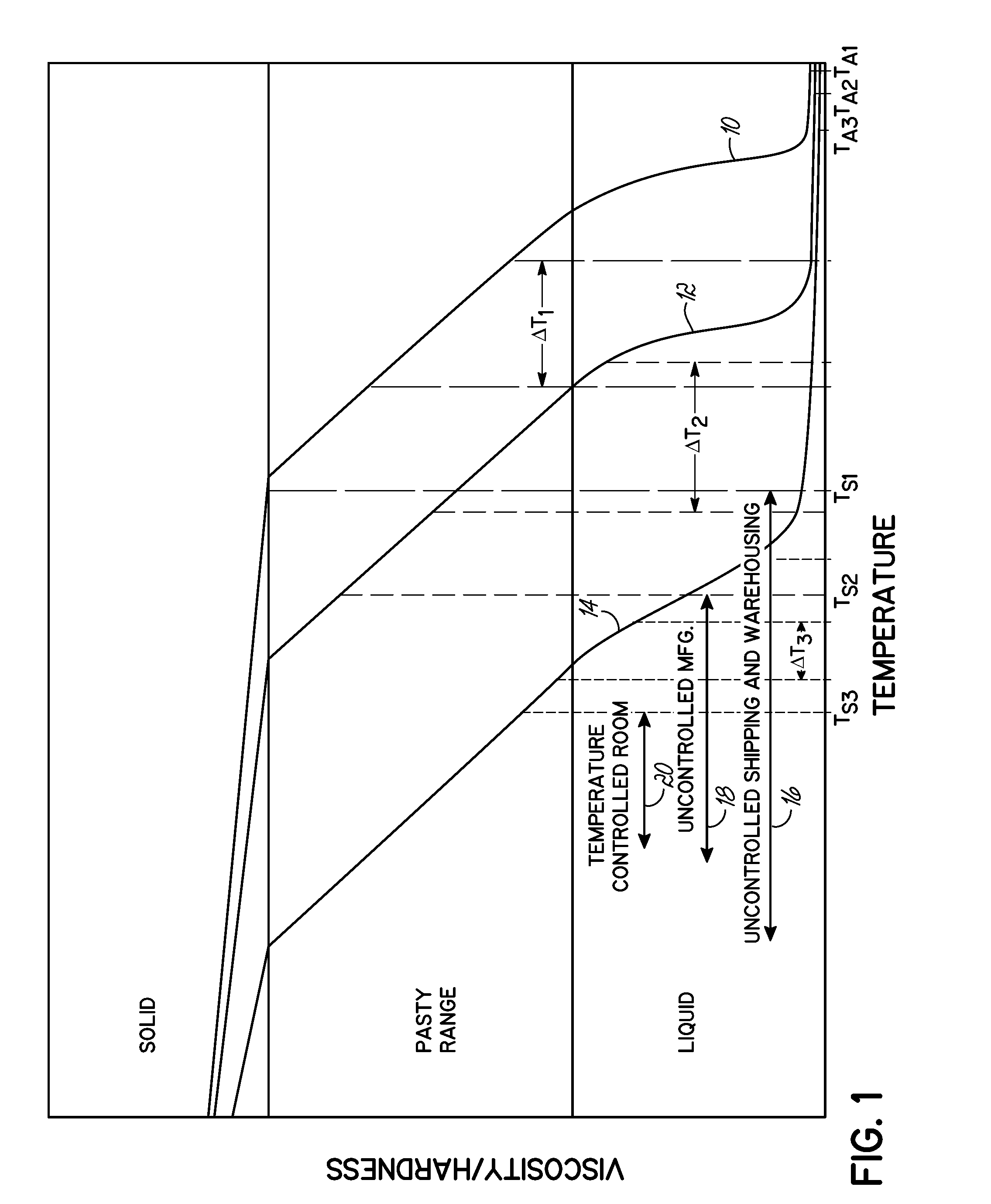
[0009]To these ends, in one embodiment of the invention, a flux for use in soldering comprises a primary solids constituent that is present in an amount greater than about 50 wt. % and one or more secondary constituents that is selected from solvents, thickeners, and/or metal oxide reducing agents. The flux has a temperature profile in which the flux is in a non-flowable inactive state at temperatures at and below a max

Problems solved by technology

Even though current solder pastes facilitate forming consistent, quality solder joints, there are difficulties with their use due to the pastes being temperature sensitive, in the sense that the pastes degrade or deteriorate when exposed to temperatures at or above room temperature prior to soldering.
Specifically, with regard to temperature sensitivity, if the solder paste is exposed for prolonged periods at temperatures even as high as room temperature, it may gradually lose its beneficial attributes.
Moreover, exposing the solder paste to greater temperatures hastens its deterioration.
Consequently, current pastes are viewed as having a limited shelf life at and above room temperatures.
Typical refrigeration temperatures include temperatures generated by commercially available refrigeration or air conditioning equipment, such temperatures being generally below 10° C. However, refrigeration has significant drawbacks.
Most notably, there are high capital and operational costs associated with using refrigeration equipment.
Thus, solder pastes are not used in these environments because their beneficial attributes are limited or destroyed prior to the time that these benefits may be fully realized and because of the lack of a cost effective solution to these problems.
Another problem that limits or renders difficult the use of current solder pastes is that the solder paste remains soft or pasty following deposition.
For example, problems arise when the solder paste is pre-deposited on the part but the actual soldering operation is performed at a later time and / or at another manufacturing facility.
In the interim period between the deposition and the soldering operations, if the part is stored and / or handled, foreign objects may contact, rub against, or become stuck in the soft solder paste.
In addition to the problems encountered due to foreign material being stuck to the paste, the paste may stick to the foreign object and adhere to that surface.
This type of contact depletes the original deposit of paste, and, in extreme situations, the original deposit may be significantly depleted or even completely removed from the targeted surface.
Additionally, the paste may inadvertently transfer to surfaces where the paste or solder alloy is detrimental to the part.
In any event, the pasty, flowable nature of the paste at around room temperature limits post-deposition operations and may add to the manufacturing costs.
While refrigerating the solder paste may improve the shelf life of the solder paste, it may not result in the solder paste becoming non-pasty at these temperatures.
In other words, a cold solder paste may have all of the above-mentioned inadvertent transfer issues.
In addition to the cost considerations set forth above, refrigeration is not generally a solution to preserve the deposited solder pastes.
However, as noted, such a process requires that the part be heated at least one additional time which may be counterproductive since, in the case of electronic assemblies, the parts themselves may be temperature sensitive.
The additional heating cycle may increase the number of component failures.
Furthermore, the flux remains tacky such that a release sheet is attached to the flux to prevent contamination.

Method used


Image

  • Flux and solder material and method of making same
  • Flux and solder material and method of making same

Examples


example

[0047]A flux that is solid at room temperature was prepared. The flux contained 80 wt. % partially hydrogenated rosin having a softening temperature of approximately 80° C. and an acid value of 150-170, 15 wt. % polyethylene glycol 1450, 2.5 wt. % azelaic acid, and 2.5 wt. % stearic acid.

[0048]A solder material was prepared by dispersing solder particles in the above flux. The solder material contained 85 wt. % solder particles of 96.5Sn-3Ag-0.5Cu alloy with the above flux forming the balance of the solder material. At 22° C., the solder material was solid. The deposition temperature range was roughly 45° C. to 60° C. The activation temperature was approximately 95° C.

[0049]In another embodiment, a method of making the flux includes heating the primary solids constituent to a liquid state. While the primary solids constituent is in the liquid state, the one or more secondary constituents are added to form a flux mixture. The flux mixture is cooled to a temperature at or below the ma...


PUM

PropertyMeasurementUnit
Temperatureaaaaaaaaaa

Abstract

A flux for use in soldering comprises a primary solids constituent present in an amount greater than about 50 wt. % and one or more secondary constituents that is selected from solvents, thickeners, and / or metal oxide reducing agents. The flux has a temperature profile in which the flux is in a non-flowable inactive state at temperatures at and below a maximum storage temperature that is above about 27° C., a liquid active state at an activation temperature, and a flowable inactive state in a deposition temperature range above the maximum storage temperature and below the activation temperature. A solder material comprises solder particles dispersed in the flux.

Description

CROSS-REFERENCE TO RELATED APPLICATION[0001]This application claims the benefit of the filing date of U.S. Patent Application Ser. No. 61 / 302,721, entitled “FLUX AND SOLDER MATERIAL AND METHOD OF MAKING SAME” filed on Feb. 9, 2010, the disclosure of which is incorporated by reference herein in its entirety.FIELD OF THE INVENTION[0002]This invention generally relates to solder fluxes and solder materials and, more particularly, to solder fluxes and solder materials having a predetermined temperature-viscosity relationship.BACKGROUND OF THE INVENTION[0003]During a soldering process, two or more parts are joined to one another with a solder. As is known in the art, and by definition, solder is an alloy or filler metal having a liquidus temperature not exceeding 450° C. (840° F.). While in contact with the parts to be joined, the solder is melted and flows into the joint by capillary action. Upon cooling the molten solder, a permanent joint is formed between the parts. One common applic...

Claims


Application Information

Patent Timeline
IPC IPC(8): B32B1/08B23K35/34B32B15/01B32B15/02B23K31/02
CPCB23K35/0244Y10T428/2951B23K35/36B23K35/3613B23K35/3618B23K35/362B23K35/368B23K35/40B32B15/01B32B15/02B32B15/04H05K3/3489Y10T428/12292Y10T428/12493B23K35/025Y10T428/31678
Inventor VIVARI, JR., JOHN A.
Owner NORDSON CORP
Why Eureka
Try Eureka