
Gas Scrubbed Perfusion Filter

a technology of perfusion filter and gas scrubber, which is applied in the direction of peptides, filtration separation, separation processes, etc., can solve the problems of low cell densities, high cost of operation, and product formation is often inhibited, so as to reduce the risk of contamination and cost. , the effect of low cos

Inactive Publication Date: 2011-08-18
NIAZI SARFARAZ K
View PDF13 Cites 10 Cited by
  • Summary
  • Abstract
  • Description
  • Claims
  • Application Information

AI Technical Summary

Benefits of technology

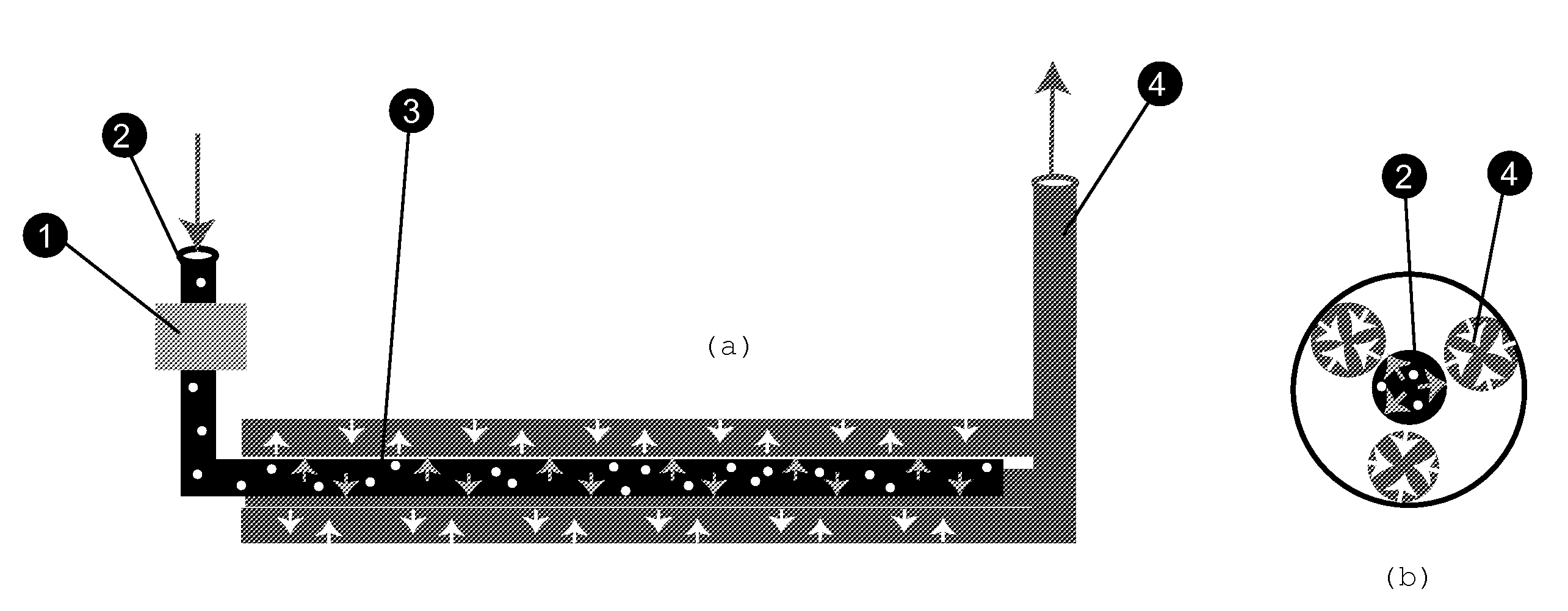
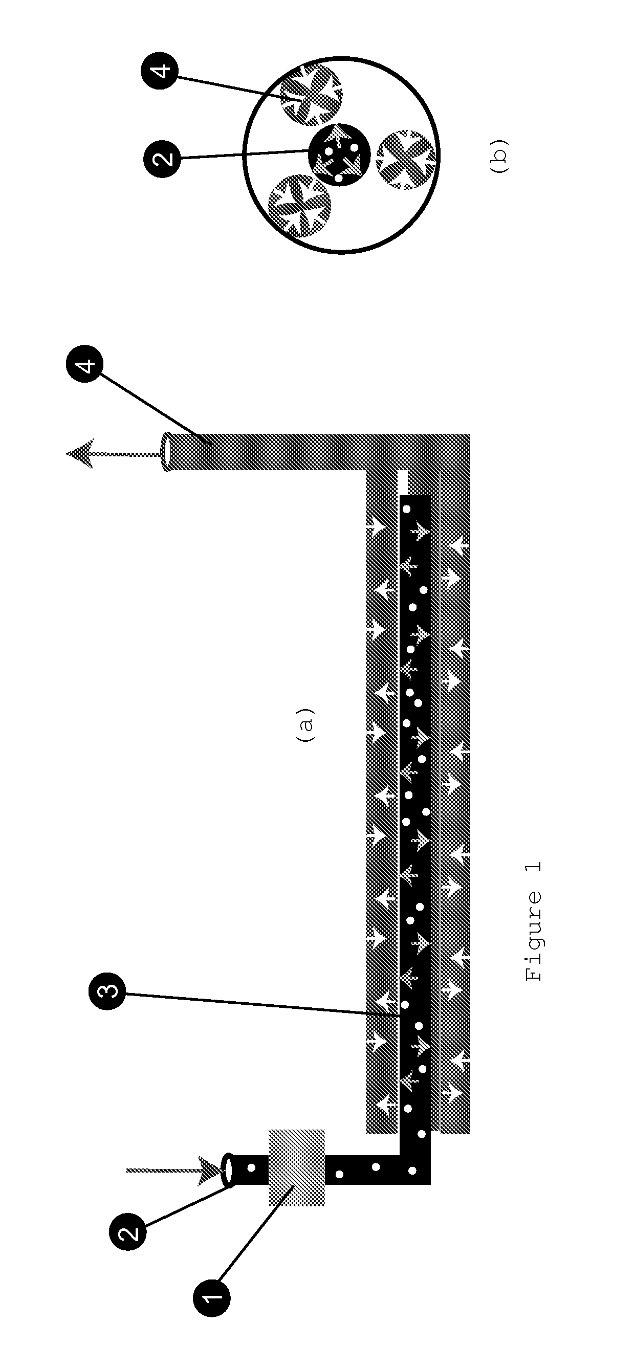
[0017]A flexible tube (harvesting tube) allows the essentially cell-free filtrate to be drawn out from inside the filter. The gas scrubbing action serves to clean the filter and allows it to operate without clogging for weeks and months. Nutrient feed is pumped into the bioreactor and the harvest filtrate is removed continuously, or at periodic intervals.
[0019]The perfusion bioreactor may be used to produce secreted products, produce large amounts of slow growing cells, or function as an artificial organ such as an extracorporeal liver. The simple construction and sterile design of the filter assembly make it ideal for hospital use in cell and gene therapy applications.

Problems solved by technology

One limitation to the use of this technology is the high cost of operation.
This method has several drawbacks: firstly, a large fraction of nutrients are wasted in simply growing up cells and are not used directly for making the product; secondly, product formation is often inhibited due to the buildup of toxic metabolic byproducts; and lastly critical nutrients are often depleted leading to low cell densities and consequently lower product yields.
Without perfusion, cells in culture go through alternating phases of being fed and starved, thus limiting full expression of their growth and metabolic potential.
The greatest challenge of perfusion cell culture has always been the need to contain the cells within the culture without reducing cell viability.
All of these steps add substantial cost to the manufacturing process.
However, like other such methods, these devices have high cost and limited applications.
The central problem in perfusion culture is how to retain the cells in the bioreactor.
The major problem with settlers is the varying sedimentation characteristics of different cells and the difficulty in scale-up to industrial systems.
Centrifugation has found limited application in cell culture due to the difficulty in maintaining sterility.
The first three methods share a common weakness—in that the liquid from the bioreactor must be pumped through the separation device and the cell-enriched material returned to the bioreactor.
Keeping this recirculation loop sterile is difficult, and contamination often occurs.
To maintain the high cross-flow velocity necessary to prevent clogging, the cells are subjected to high pumping shear in the recirculation loop and are often damaged.
Oxygen depletion can also occur if the pumping rate is too slow.
These factors often lead to degradation in product quality and quantity.
However, the method of removing nutrient media from a bioreactor and replacing it with fresh media becomes a difficult process when using thousand of liters of nutrient media and very high density of cell culture, as it is becoming a normal exercise in commercial production.
Whether it is placing the filter in a special place in the bioreactor to reduce exposure to high cell titer or gently shaking the filter to keep the filter from getting clogged, these prior art methods are inadequate for large-scale commercial production.
Even if the perfusion is performed at a rate of one to two media volume exchanged per day, bioreactors containing thousands of liters with suspension culture at high titer would make it impossible to use any of the current art to accomplish the filtration and harvesting of the nutrient media.
Large-scale filtration would require faster passage of media through the filter and that would inevitably bring cell culture in direct contact with filter surface resulting in fouling and blockage of the filters.
Unfortunately, the flexible and disposable bioreactors wherein most of the art of perfusion filtration is developed are not suitable for large-scale operations and thus the dearth of technology in the field of cell culture processing was not fully appreciated.

Method used


Image

  • Gas Scrubbed Perfusion Filter
  • Gas Scrubbed Perfusion Filter

Examples


first embodiment

[0036]In a first embodiment, the instant invention discloses a filtration assembly comprising a perfusion filter capable of separating suspended cells from the media, a gas sparger and an arrangement of the two in such configuration that the outer surface of the perfusion filter is continuously bathed in the fine bubble created by the sparging filter. This allows continuous scrubbing of the external surface of the perfusion filter and keeping the surface clean at all time for long-term perfusion.

second embodiment

[0037]In a second embodiment, the instant invention discloses a design of a perfusion filter comprising a hard tubular structure with perforated surface, which is sheathed with a filter membrane of any type; the tubular structure provides the support to the filter membranes, which are often delicate and flexible.

third embodiment

[0038]In a third embodiment, the instant invention discloses the use of ceramic material structures such as tube, disc, ovoid or rectangle to serve as perfusion filter with pore sizes of 5 micron or less.

[0039]In a third embodiment, the instant invention disclose the use of ceramic material structures such as tube, disc, ovoid or rectangle to serve as sparging filter with pore size of 10 micron or less.


PUM

PropertyMeasurementUnit
Lengthaaaaaaaaaa
Pore sizeaaaaaaaaaa
Flow rateaaaaaaaaaa

Abstract

Fine gas bubbles traveling at fast speed are employed to scrub a hard-surface filter for harvesting liquids from suspensions including those consisting of nutrient media and cell culture, on a continuous basis without clogging the filters.

Description

FIELD OF THE INVENTION[0001]The present invention generally relates to systems and methods for perfusion operations in a bioreactor. The invention has applications in the culture of animal, insect, and plant cells, for the production of secreted substances such as proteins, antibodies, polypeptides, and viruses. Applications include medical areas such as artificial organs and cell therapy.BACKGROUND OF THE INVENTION[0002]Cell culture has generated considerable interest in recent years due to the revolution in genetic engineering and biotechnology. Cells are cultured to make proteins, receptors, vaccines, and antibodies for therapy, research, and for diagnostics.[0003]One limitation to the use of this technology is the high cost of operation. Traditionally, cell culture has been operated in a batch mode. In batch operation, the bioreactor is seeded with a small amount of cells and the cells are grown to high density. The cells secrete the product of interest and eventually die due to...

Claims


Application Information

Patent Timeline
IPC IPC(8): C12M1/12C12P1/00C12M1/36A01N1/02
CPCA01N1/0247C12M23/26B01D29/64C12M29/10B01D29/114C12M29/04C12M47/02C12M21/00B01D29/15B01D29/66C07K1/34C07K14/505C12M47/10C12N1/20
Inventor NIAZI, SARFARAZ K.
Owner NIAZI SARFARAZ K
Learn More