
Nanowire Structural Element

a technology of nanowires and structural elements, applied in the direction of raney catalysts, catalyst activation/preparation, metal/metal-oxide/metal-hydroxide catalysts, etc., can solve the problems of loss of contact between nanoparticles, major problems in the stabilization of these, limited catalyst surface to the walls of the reactor, etc., to ensure the stability of the network and high long-term stability

Active Publication Date: 2011-09-01
GSI HELMHOLTZZENT FUR SCHWERIONENFORSCHUNG
View PDF8 Cites 2 Cited by
  • Summary
  • Abstract
  • Description
  • Claims
  • Application Information

AI Technical Summary

Benefits of technology

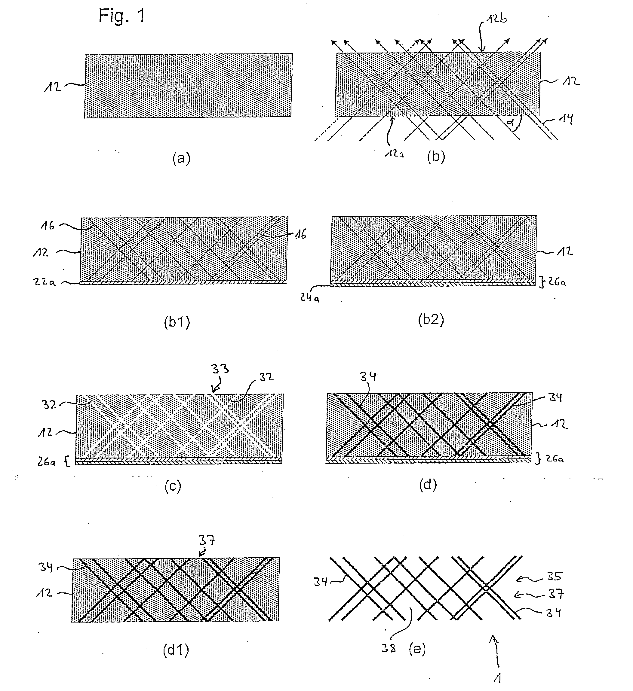
"The invention provides a new type of nanowire structural element and a process for producing it. The nanowire structural element has a stable hollow chamber-like structure with a large interaction surface area. It can be used in various ways, such as a catalytic element. The process involves irradiating a template foil with high-energy radiation to create latent tracks in the foil. The latent tracks are then used to create a nanopore network with intersecting channels. A cathode layer is applied to the foil before etching the latent tracks to form continuous channels that penetrate the foil. Nanowires are then grown in the nanopores. The technical effects of this invention include a new type of nanowire structural element with a large interaction surface area and a process for producing it."

Problems solved by technology

This means however that the catalytic surface is limited to the walls of the reactor.
The stabilization of these is a major problem.
1. Loss of contact between nanoparticles due to corrosion of the carrier.
2. Dissolving and renewed deposition or Ostwald ripening.
3. Aggregation of the nanoparticles in order to minimize the surface energy.
4. Dissolving of the nanoparticles and migration of the dissolvable ions.
In these cases however, the nanostructures are not particularly stable.
With these processes however, only single nanowires were obtained.

Method used


Image

  • Nanowire Structural Element
  • Nanowire Structural Element
  • Nanowire Structural Element

Examples


example 1

[0082]For the production of a nanowire structural element 1, a 30 μm thick circular shaped (r=1.5 cm) polycarbonate foil 12 (Macrofol®) irradiated with heavy ions 14 having an energy of 11.1 MeV / u and at two angles (+45°, −45° each having a fluence of 5×10⁸ ions / cm2 is used. Prior to the application of the conductive metallic layer 22a, each side of the polymer foil 12 is irradiated for one hour with UV light, in order to increase the selectivity of the etching along the tracks 16.

[0083]A gold layer 22a is sputtered onto the first side 12a of the polymer foil 12, having a thickness of ca. 30 nm (b1). This is reinforced by a potentiostatic deposition of copper from a CuSO4 based electrolyte solution (Cupatierbad, Riedel) with a voltage of U=−500 mV, wherein a copper rod electrode serves as the anode (partial step 24a) (b2). The deposition is stopped after 30 minutes, at which point the copper layer 24a is approx. 10 μm thick. Subsequently, etching is carried out from the untreated si...

example 2

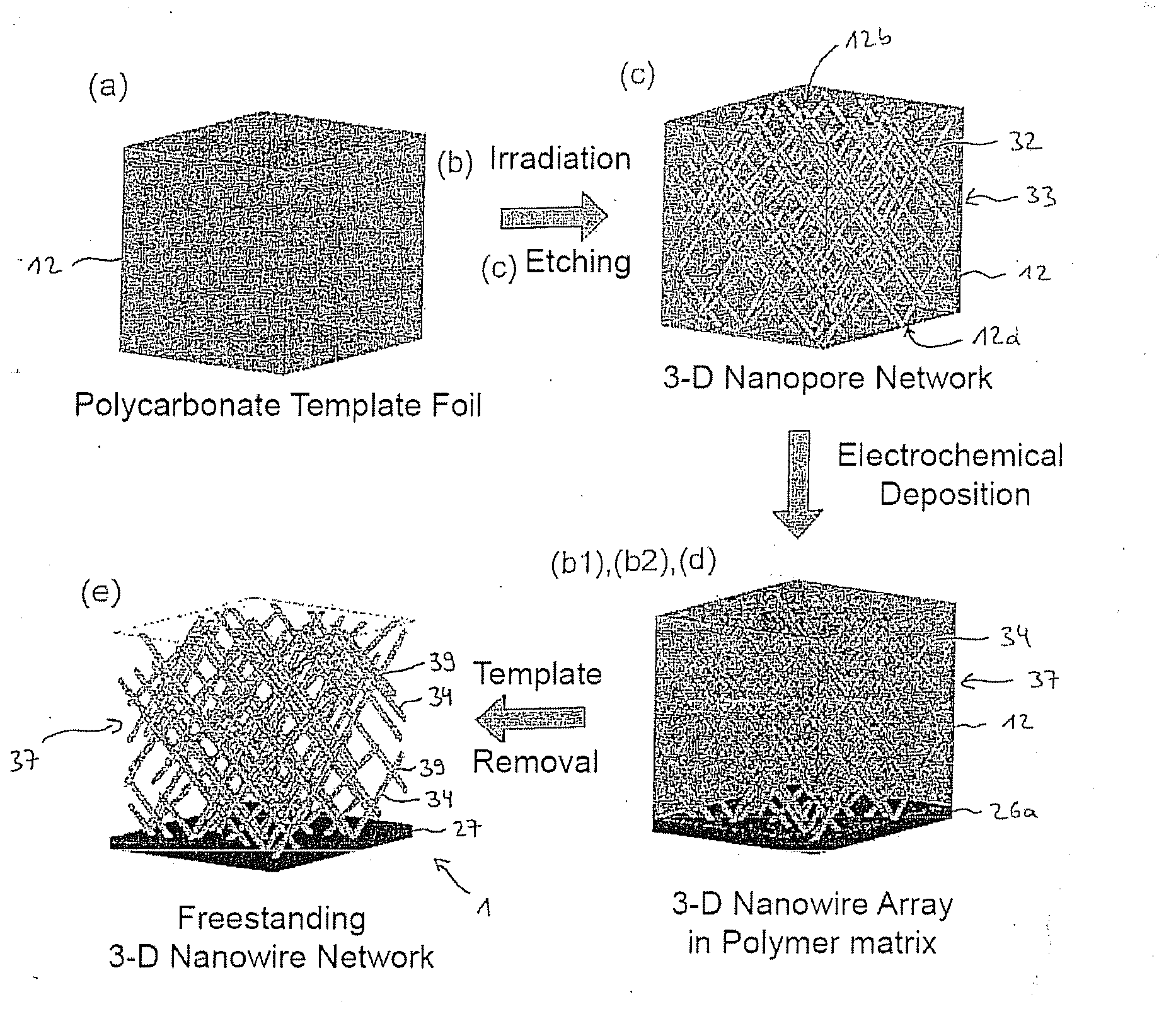
[0088]In reference to FIGS. 7-10, a further embodiment is produced. FIG. 7 shows schematically, and partially summarized the following partial steps of the process:

(a) Preparation of the template foil,

(b), (c) Irradiation and etching of the ion tracks to form nanopores,

(b1), (b2), (d) Generation of a cathode layer and deposition of the nanowires in the nanopores,

(e) Dissolving and removal of the template foil.

[0089]With reference to FIG. 7, the template foil or polymer membrane 12 is irradiated from more than two different directions. The irradiation is carried out in this example from four different directions, wherein the four irradiation directions are not in the same plane. With reference to perspective view shown in FIG. 7, radiation is applied in each case once from each of the four sides diagonally from above, and this being at a polar angle of 45° to the surface of the substrate and at azimuth angles of 0°, 90° 180° and 270°. The template foil 12 is therefore rotated at leas...


PUM

PropertyMeasurementUnit
diameteraaaaaaaaaa
diameteraaaaaaaaaa
diametersaaaaaaaaaa

Abstract

The invention concerns a nanowire structural element suited for use in a microreactor system or microcatalyzer system.A template based process is used for the production of the nanowire structural element, wherein the nanowires are electrochemically depositioned in the nanopores. The irradiation is carried out at different angles, such that a nanowire network is formed. The hollow chamber-like structure in the nanowire network is established through the dissolving of the template foil and removal of the dissolved template material. The interconnecting of the nanowires provides stability to the nanowire structural element and an electrical connection between the nanowires is created thereby.

Description

FIELD OF THE INVENTION[0001]The invention concerns a nanowire structural element, a process for production of said and a micro-reactor system, specifically a microcatalyzer system.BACKGROUND OF THE INVENTION[0002]In “Chemistry in Microstructured Reactors,” Ang. Chem. Int. Ed. 2004, 43, 406-466 [: Applied Chemistry, International Edition], K. Jähnisch et al. have demonstrated the advantages that microstructured components have in chemical reactions and for analytical purposes. This has led to an increase in the importance that such systems have for chemical synthesis and analysis. In comparison to conventional reactors, these microstructures have a large surface area / volume ratio, which has a positive influence on the transference of heat as well as the process of the transportation of matter (see also: O. Wörz et al. “Micro-reactors—A New Efficient Tool for Reactor Development,” Chem. Eng. Technol. 2001, 24, 138-142).[0003]Many known reactions have been carried out in microstructure...

Claims


Application Information

Patent Timeline
Patent Type & Authority Applications(United States)
IPC IPC(8): G01N25/00G01N33/00B01J19/00B01J37/34B01J37/02B01J35/06B82Y30/00B82Y40/00
CPCB01J19/0093Y10T29/49117B01J23/72B01J35/0006B01J2219/00783B01J2219/00835B01J2219/00846B01J2219/00853B01J2219/0086B01J2219/00873B22F1/0025B22F3/002B81B2201/0292B81B2201/051B81C99/0085B82Y15/00B82Y30/00C25D1/04C25D1/08C25D5/18C25D1/00C25D1/003Y10S977/762B82Y40/00C25D1/006Y10T428/12201Y10T428/24562Y10T428/25B01J23/42Y10T428/12389Y10T428/24893C25D5/617B22F1/0547B01J35/19G01F1/688G01N25/00
Inventor CORNELIUS, THOMASENSINGER, WOLFGANGNEUMANN, REINHARDRAUBER, MARKUS
Owner GSI HELMHOLTZZENT FUR SCHWERIONENFORSCHUNG
Learn More