
Glass roll, and method of manufacturing glass roll

Inactive Publication Date: 2011-09-08
NIPPON ELECTRIC GLASS CO LTD
View PDF4 Cites 47 Cited by
  • Summary
  • Abstract
  • Description
  • Claims
  • Application Information

AI Technical Summary

Benefits of technology

[0019]According to the invention of claim 1, provided is a method of manufacturing a glass roll, including: forming a glass film by a downdraw method; and winding the formed glass film into a roll while superposing the glass film on a protective sheet, in which the glass film and the protective sheet are wound while higher tension in a winding direction is applied to the protective sheet than to the glass film. Thus, high tension in the winding direction is not applied to the glass film, and hence it is possible to produce the glass roll free from loose winding owing to relatively high tension in the winding direction applied to the protective sheet. Because the tension in the winding direction is not applied to the glass film when winding the glass film or the tension is low, it is possible to prevent a change in curvature of a curved region during feed of the glass film along with its winding, and forming of the glass film is stabilized, with result that the glass film free from warpage, waviness, and a change in film thickness can be wound. Further, small flaws do not occur on the surface of the glass film.
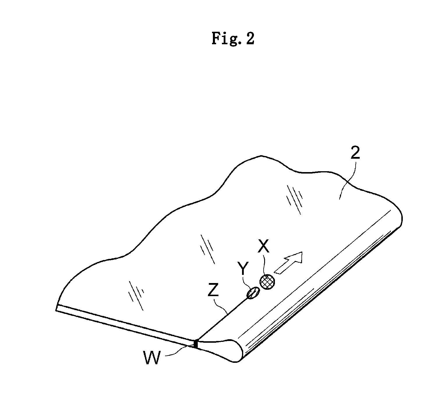
[0020]According to the invention of claim 2, a selvage portion formed at each end portion in a width direction of the glass film is cut with a laser by the time the glass film is wound into a roll. Thus, without performing post-processing such as polishing, it is possible to easily impart moderate smoothness to a cut surface constituting each end surface in the width direction of the glass film. Relatively high tension in the winding direction is applied to the protective sheet, and hence the end surface of the glass film and the protective sheet are easily held in contact with each other. However, even in the case of contact, owing to the smoothed end surface of the glass film, the end surface does not bite into the protective sheet, and hence it is possible to satisfactorily maintain separability between the glass film and the protective sheet. Further, when winding the glass film into a roll, chips resulting from small flaws are less likely to occur on the each end surface of the glass film. Thus, it is possible to reduce glass powder, which is generated due to the chips on the end surface of the glass film, and hence there is a great advantage in ensuring cleanness of the front and back surfaces of the glass film. The cutting by the laser described herein includes: laser splitting utilizing thermal stress resulting from heating by the laser and cooling by a refrigerant; and laser fusing of fusing and cutting glass by heating by the laser.
[0021]According to the invention of claim 3, the glass film and the protective sheet are wound so that the protective sheet is kept to form an outermost layer. Thus, by applying relatively high tension in the winding direction to the protective sheet, the glass film can be easily fastened. Consequently, it is possible to manufacture the glass roll free from looseness.
[0022]According to the invention of claim 4, the downdraw method includes an overflow downdraw method. Thus, it is possible to form the glass film excellent in surface smoothness without performing additional processing after the forming, and to manufacture the glass roll excellent in surface accuracy.
[0023]According to the invention of claim 5, provided is a glass roll in which higher tension in a winding direction is applied to the protective sheet than to the glass film. Thus, it is possible to provide the glass roll obtained by tightly winding the glass film free from warpage, waviness, and a change in film thickness.
[0024]According to the invention of claim 6, the glass film has a thickness of 1 μm or more and 200 μm or less. Thus, it is possible to impart appropriate flexibility to the glass film. Accordingly, it is possible to alleviate overstress applied to the glass film when winding the glass film, and to prevent the glass film from breaking.

Problems solved by technology

However, there is a problem in that the resin film is inferior to the glass plate in gas barrier property.
In a case of the OLED display, a light-emitting body to be used is deteriorated due to contact with gas, such as oxygen or water vapor, and hence the resin film inferior in barrier property cannot be used in place of the glass plate.
Further, for the same reason, also in a field other than the OLED display, the resin film cannot be used in place of the glass plate in many cases.

Method used


Image

  • Glass roll, and method of manufacturing glass roll
  • Glass roll, and method of manufacturing glass roll
  • Glass roll, and method of manufacturing glass roll

Examples


Embodiment Construction

[0029]Hereinafter, a glass roll according to the present invention and a preferred embodiment of a method of manufacturing the same are described with reference to the drawings.

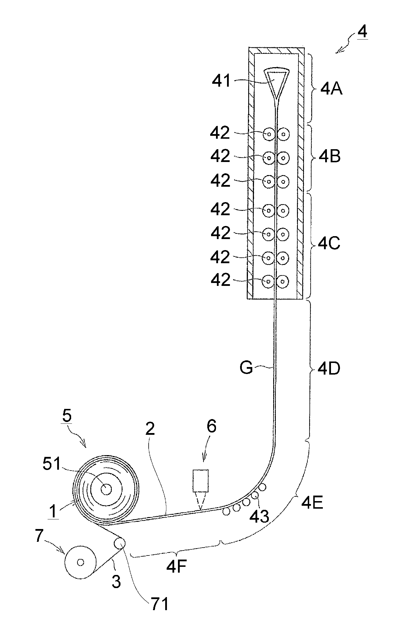
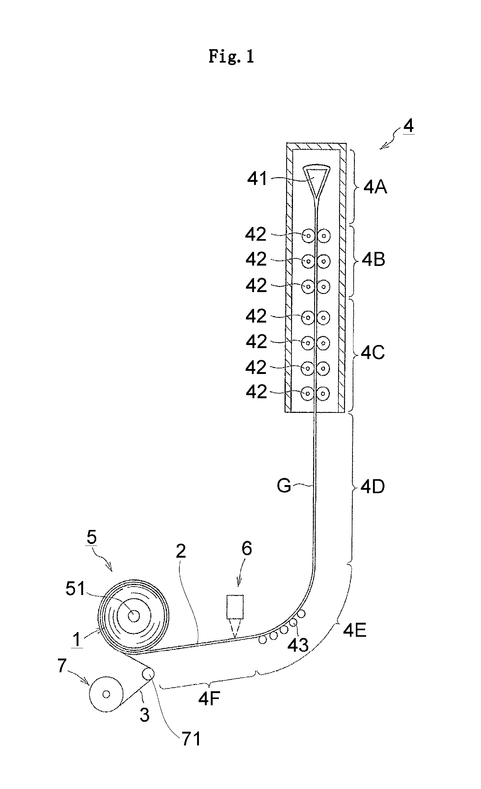
[0030]As illustrated in FIG. 1, a glass roll (1) according to the present invention is produced in such a manner that a glass film (2) is formed by a downdraw method and a protective sheet (3) is superposed on an outer peripheral side of the formed glass film (2), and then the glass film (2) and the protective sheet (3) are wound into a roll so that higher tension in a winding direction is applied to the protective sheet (3) than to the glass film (2).

[0031]Specifically, a trough (41) having a wedge-shaped outer surface in cross-section is disposed inside a forming apparatus (4), and glass (molten glass) melted in a melting furnace (not shown) is supplied into the trough (41). As a result, the molten glass overflows from a top of the trough (41). Then, the overflowing molten glass flows over both side surface...


PUM

PropertyMeasurementUnit
Thicknessaaaaaaaaaa
Thicknessaaaaaaaaaa
Surface roughnessaaaaaaaaaa

Abstract

To manufacture a roll body (glass roll) of the glass film, which is subjected to a tension application, and is free from looseness, without adversely affecting the formation of the glass film and causing a problem such as cracks, provided is a method of manufacturing a glass roll (1), including: forming a glass film (2) by a downdraw method; and winding the formed glass film (2) into a roll while superposing the glass film (2) on a protective sheet (3), in which the glass film (2) and the protective sheet (3) are wound while higher tension in a winding direction is applied to the protective sheet (3) than to the glass film.

Description

TECHNICAL FIELD[0001]The present invention relates to a glass film used for a glass substrate of a flat panel display such as a liquid crystal display or an organic light-emitting diode (OLED) display, for a glass substrate of a device such as a solar cell, a lithium ion battery, a digital signage, a touch panel, or electronic paper, for cover glass of a device such as an OLED lighting, and for a drug package. The present invention also relates to a method of manufacturing the glass roll.BACKGROUND ART[0002]In view of space saving, in recent years, there are widely used flat panel displays, such as a liquid crystal display, a plasma display, an OLED display, and a field emission display, in place of a cathode ray tube (CRT) display that has been conventionally and widely used. Such flat panel displays are required to be further thinned. In particular, the OLED display is required to allow easy carrying by being folded or wound, and to allow use not only on a flat surface but also on...

Claims


Application Information

Patent Timeline
IPC IPC(8): B32B17/06B32B3/02C03B17/06
CPCB32B3/02B32B17/064B65H18/10Y10T428/266C03B17/06Y10T428/24752Y10T428/24777B65H2301/414324B32B17/10C03B17/062C03B17/064C03B17/065C03B17/068
Inventor TERANISHI, YASUOHASEGAWA, YOSHINORIMORI, KOICHIMORI, HIROKI
Owner NIPPON ELECTRIC GLASS CO LTD
Learn More