
Garnet-based phosphor ceramic sheets for light emitting device

a technology of phosphor ceramic sheets and light emitting devices, which is applied in the direction of discharge tubes/lamp details, electrical equipment, basic electric elements, etc., can solve the problems of yellow emitting light from yag powders being back scattered and dispersed as a loss of white light emission, and strong light scattering

Inactive Publication Date: 2011-09-22
NITTO DENKO CORP
View PDF13 Cites 95 Cited by
  • Summary
  • Abstract
  • Description
  • Claims
  • Application Information

AI Technical Summary

Problems solved by technology

However, since the particle size of YAG phosphor powder utilized for this system is around 1-10 μm, the YAG powders dispersed in the encapsulant resin medium can cause strong light scattering.
As a result, a considerable portion of both the incident light from the blue LED and the yellow emitting light from YAG powders ends up being back scattered and dissipated as a loss of white light emission.
However, these nitride or sulfide emissive elements are not desirable due to the processing difficulties and / or chemical / thermal stability concerns.

Method used


Image

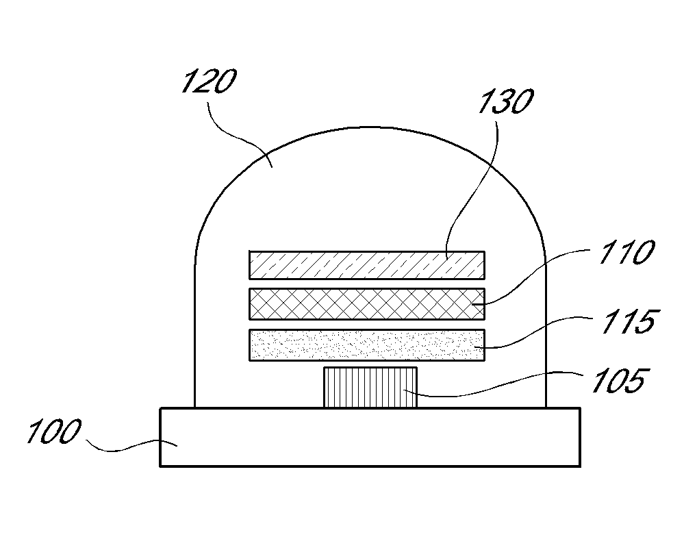
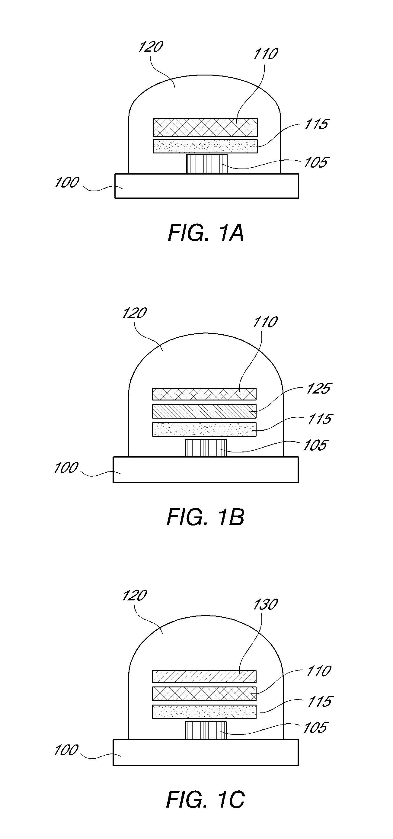
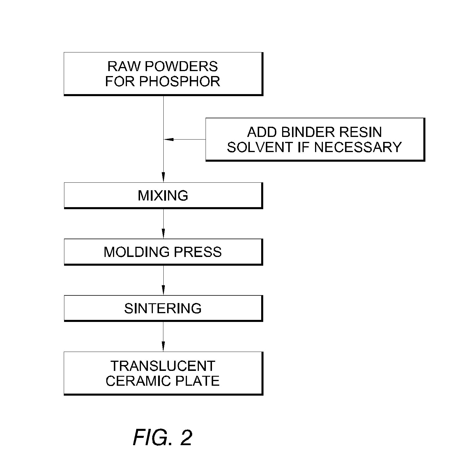
  • Garnet-based phosphor ceramic sheets for light emitting device
  • Garnet-based phosphor ceramic sheets for light emitting device
  • Garnet-based phosphor ceramic sheets for light emitting device

Examples


example 1

Warm White Light Emitting Composite

The following example demonstrates forming a composite for the emission of warm white light.

example 1.1

YAG:Ce

0.14923 mol (14.29 g) of Yttrium (III) nitrate hexahydrate (99.9% pure, Sigma-Aldrich), 0.25 mol (23.45 g) of Aluminum nitrate nonahydrate (99.97% pure, Sigma-Aldrich), and 0.015 mol (0.081 g) of Cerium (III) nitrate hexahydrate (99.99% pure, Sigma-Aldrich) were dissolved in 250 ml of deionized water, followed by ultrasonication for 30 min to prepare the transparent precursor solution. This pre-cursor solution of 0.4 M was carried into a plasma reaction chamber via an atomization probe using a liquid pump.

All deposition experiments were conducted with an RF induction plasma torch (TEKNA Plasma System, Inc PL-35) operating at 3.3 MHz. For the deposition experiments, the chamber pressure was kept at around 25 kPa-35 kPa, and the RF generator plate power was in the range of 10-12 kW. Both the plate power and the deposition pressure are user-controlled parameters. Argon was introduced into the plasma torch as both the swirling sheath gas and the central plasma gas via the gas inle...

example 1.2

Lu2CaMg2Si3O12:Ce

The procedure of Example 1.1 was followed except that 52.612 g of Lutetium nitrate hydrate (46.8% pure, Metall Rare Earth Limited, ShenZhen, P.R.China), 14.899 g of Calcium nitrate tetrahydrate (99% pure, Sigma-Aldrich), 32.374 g of Magnesium nitrate hexahydrate (99% pure, Fluka), 102.908 g of Aminopropylsilanetriol (25% in water, Gelest), and 0.543 g of Cerium (III) nitrate hexahydrate (99.99% pure, Sigma-Aldrich) were dissolved in 250 ml of deionized water, followed by ultrasonication for 30 min to prepare the transparent precursor solution. This precursor solution of 0.4 M was carried into a plasma reaction chamber via an atomization probe using a liquid pump.


PUM

PropertyMeasurementUnit
Fractionaaaaaaaaaa
Wavelengthaaaaaaaaaa

Abstract

Some embodiments disclosed herein include a lighting apparatus having a composite. The composite may include a first emissive layer and a second emissive layer. The first emissive layer may include a first garnet phosphor having a common dopant. The second emissive layer may include a second garnet phosphor having the common dopant. In some embodiments, the first emissive layer and the second emissive layer are fixed together. Some embodiments disclosed herein include efficient and economic methods of making the composite. The method may include, in some embodiments, sintering an assembly that includes pre-cursor materials for the first emissive layer and the second emissive layer.

Description

BACKGROUND1. FieldThe present application relates to a lighting apparatus including a translucent composite of garnet-based emissive layers.2. DescriptionSolid state light emitting devices such as light emitting diode (LED), organic light emitting diode (OLED) or sometimes called organic electroluminescent device (OEL), and inorganic electroluminescent device (IEL) have been widely utilized for various applications such as flat panel display, indicator for various instrument, signboard, and ornamental illumination, etc. As the emission efficiency of these light emitting devices continues to improve, applications that require much higher luminance intensity, such as automobile headlights and general lighting, may soon become feasible. For these applications, white-LED is one of the promising candidates and have attracted much attention.Conventional white-LED have been manufactured based on the combination of blue-LED and yellow light-emitting YAG phosphor powder dispersed in plastic ...

Claims


Application Information

Patent Timeline
IPC IPC(8): H01J1/63C09K11/78
CPCB32B18/00H01L33/507C04B35/44C04B35/62665C04B35/63416C04B35/6342C04B35/6344C04B35/63488C04B35/638C04B2235/3206C04B2235/3208C04B2235/3224C04B2235/3225C04B2235/3227C04B2235/3229C04B2235/3418C04B2235/604C04B2235/6562C04B2235/6565C04B2235/6567C04B2235/6581C04B2235/6587C04B2235/661C04B2235/663C04B2235/9661C04B2237/341C04B2237/343C09K11/7774H01L33/504C04B35/22C09K11/77742
Inventor ZHANG, BINMUKHERJEE, RAJESHFUJII, HIRONAKAMIYAGAWA, HIROAKIGUANG, PANNAKAMURA, TOSHITAKAMOCHIZUKI, AMANE
Owner NITTO DENKO CORP
Learn More