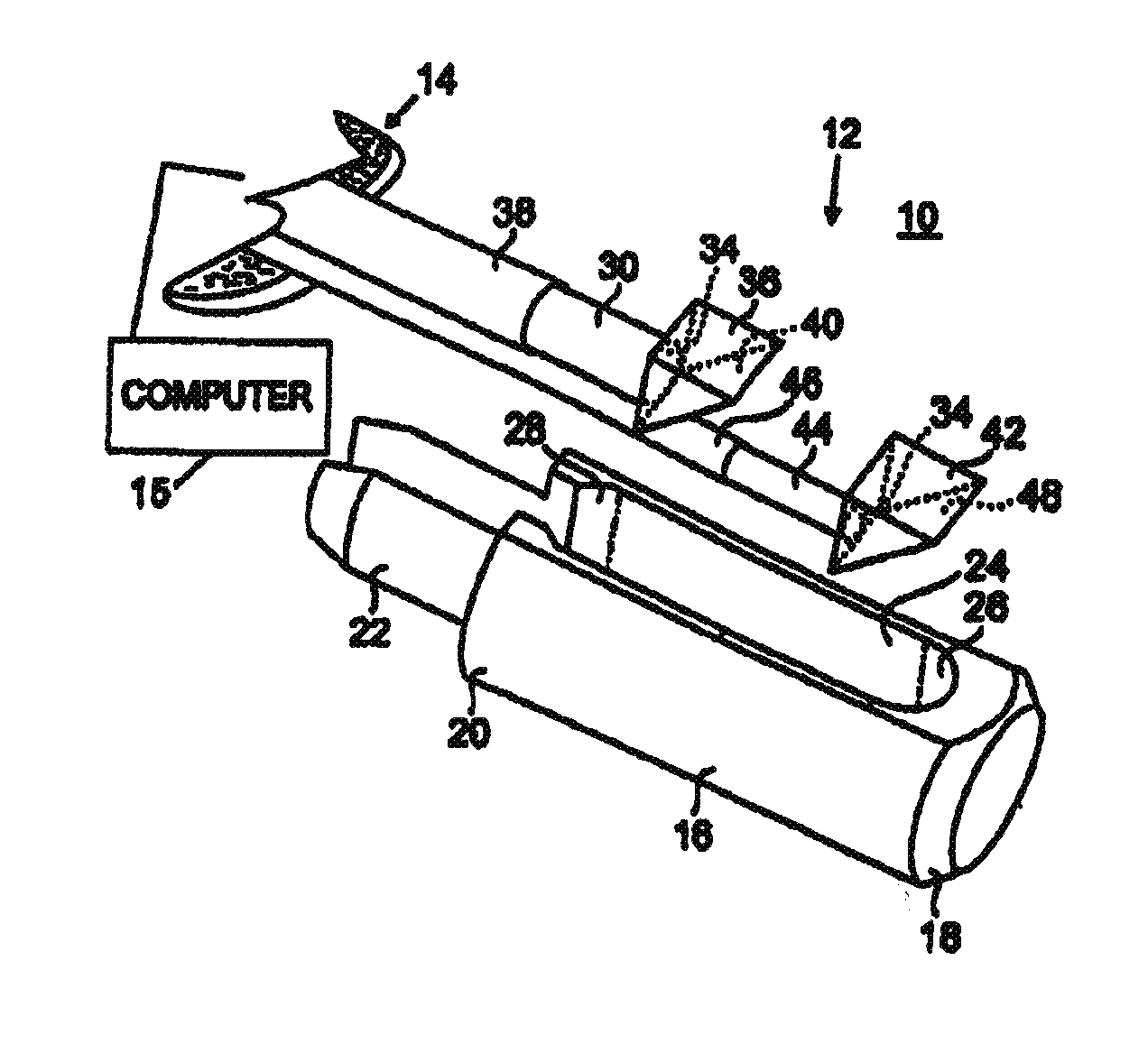
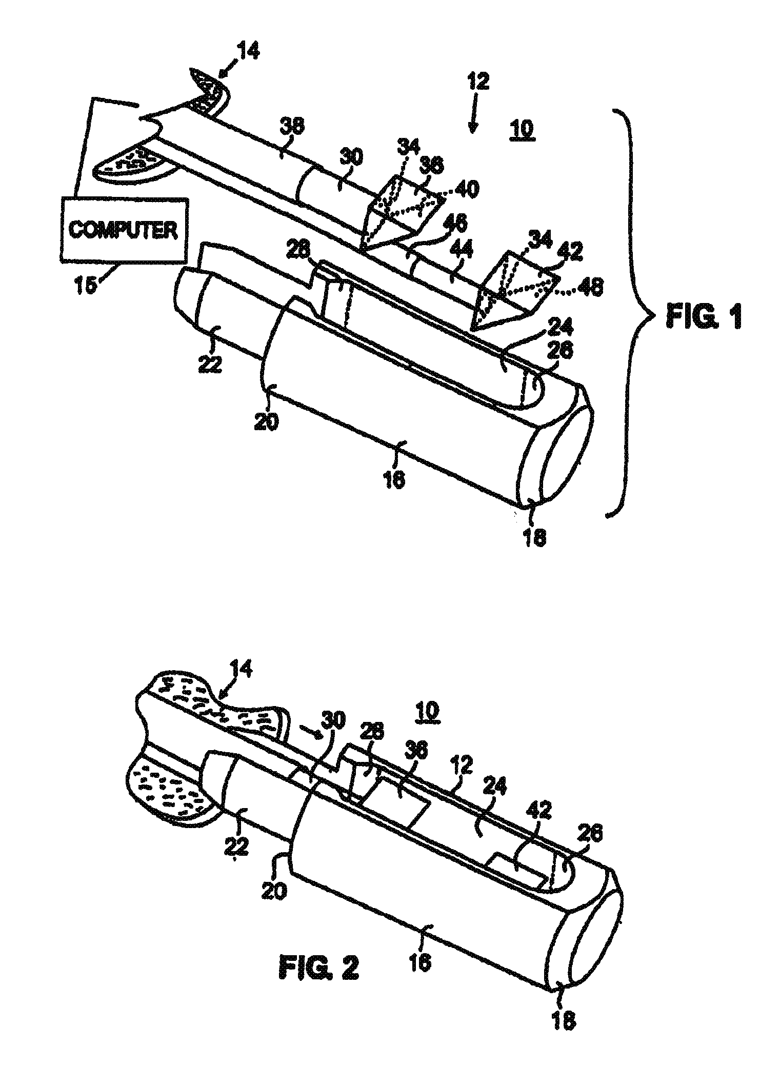
[0010]The collector
fiber arrangement in this particular embodiment includes an elongated flexible collection fiber having a distal end to which a reflector or reflective surface (i.e., a mirror member) is attached. The collection fiber has an outer buffer such as a sheath for protection of the fiber and to minimize
stray radiation therefrom. A mirror member has an angularly disposed reflective surface thereon. The delivery reflector (or mirror member) is attached to an optical delivery fiber which is enclosed similarly by an outer buffer such as a sheath for protection of the fiber and for minimization of light leakage. The delivery reflector or mirror member has an angled reflective surface thereon. The collection fiber and reflector and the delivery fiber and reflector jointly mate within the elongated receiving groove within the stem and tip housing. The elongated groove is preferably shaped to effect accurate positioning of the respective reflectors or mirror members therein, so as to emit
radiation from the delivery reflector (or mirror member) and receive
radiation reflected back from a
body tissue sample in the collection reflector (or mirror member). Once the collection and delivery fibers are within the housing, those joint fibers may be inserted within an elongated catheter shaft or rotatable coil as will be described hereinbelow.
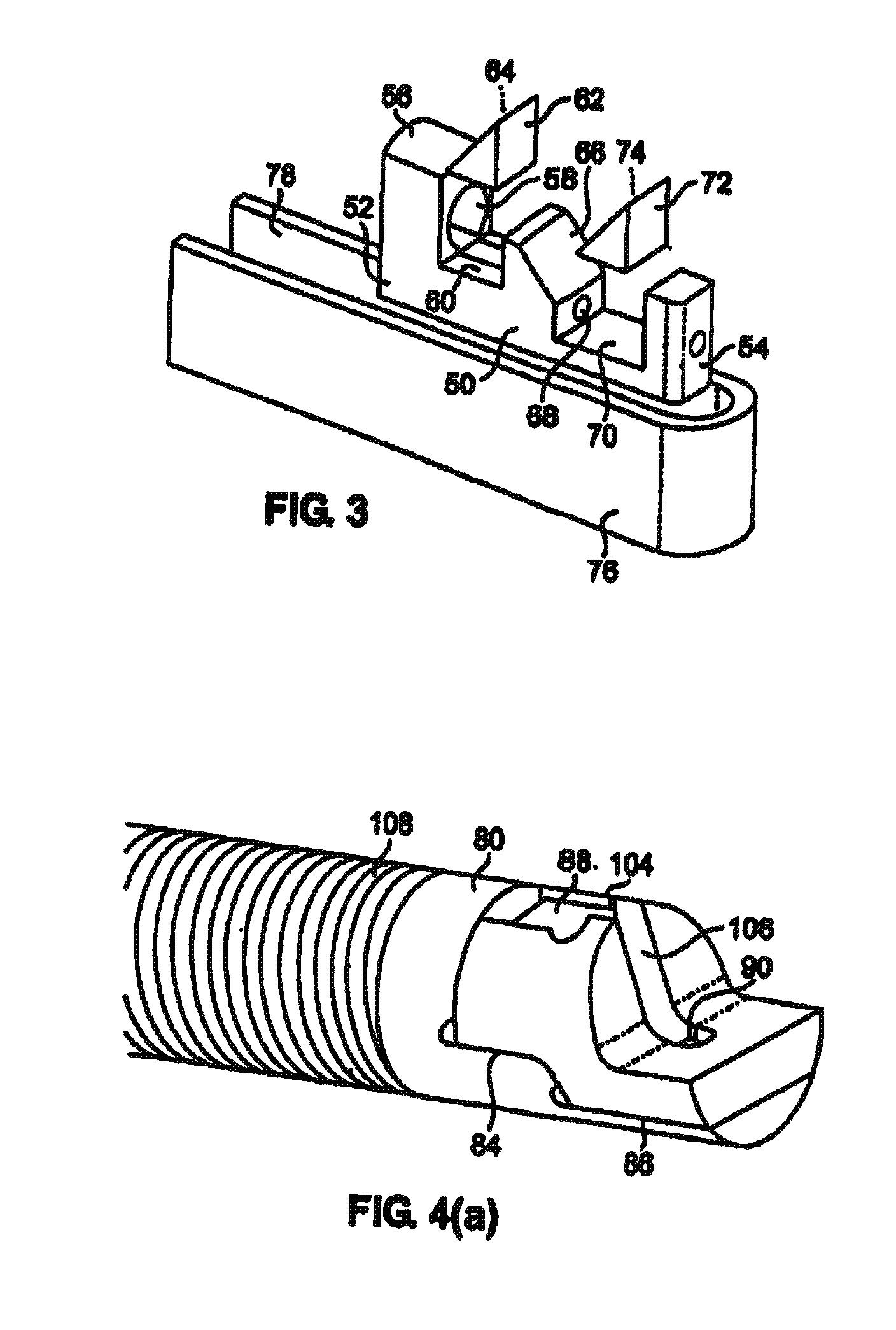
[0015]A yet further embodiment of the present invention relates to a method of constructing a catheter tip arrangement for support of a plurality of optical fibers, which support construction permits minimization of component size and adaptive angularity of reflection of the delivery and collection beams. Such a support may be accomplished by micromachining construction where additive
processing such as for example: plating,
sputtering, vapor deposition, and subtractive
processing such as for example:
etching,
laser cutting and
ablation, permits finite adjustment to the dimensions. The support comprises a base upon which an arrangement of parallel bosses are “grown”, the bosses defining between them, a pair of parallel slots into which a delivery and a collection fiber may be mated. A mirror surface and support struts are spaced at the distalmost location of the fibers, which mirror surface may be curved or manipulably bent to the desired angle for maximizing optical analysis and tissue treatment thereby. This embodiment contemplates the use of index-matching fluids added to any gap between a
catheter sheath surrounding the fibers to reduce any back reflections from the interior of the protective sheath / transmission window.
[0017]The present invention also comprises a catheter tip apparatus arranged in a catheter for the delivery and collection of an energy
signal to permit subsequent
computerized analysis of body tissue by the collected signal. The apparatus comprises an elongated housing having a longitudinal axis of rotation, the housing having a first reflective surface disposed thereon, a second reflective surface disposed on the housing distally of the first reflective surface and in axial alignment therewith; and a
first light conductive fiber in light coupled communication with the first reflective surface and a second light conductive fiber in light coupled communication with the second reflective surface, the
first light conductive fiber in communication being in communication with a controlled analytical-light generating source and the second light conductive fiber being in communication with a light-
collection analysis device. The first reflective surface may be dimensionally larger than the second reflective surface. The first reflective surface may be curvilinear. The first reflective surface may be non-parallel with respect to the second reflective surface. At least one of the first and second
reflective surfaces may be spaced apart from the light conductive fibers. The first reflective surface may be disposed radially within and spaced from the perimeter of the housing to permit a spreading of a
light beam from the first reflective surface onto the body tissue. An index matching fluid may be arranged between a distal end of the conductive fiber and the reflective surface. The reflective surface may be positioned in a holding pocket arranged in the housing. The reflective surface may be comprised of a mirrored surface. The holding pocket may be utilized to align the reflective surface with respect to the housing. The conductive light fibers may be each individually arranged within a bore disposed within the housing. The
light delivery fibers may be equally diametrically opposed about the axis of rotation of the housing to provide balance thereto and minimize eccentricity during rotation thereof.
[0022]The invention may also include a method of delivering and collecting a tissue-striking
light energy signal from a
first light fiber and adjacent delivery reflector and returning said
light energy signal to a collection reflector adjacent a second light fiber for analysis and tissue treatment. The method includes spacing the collection reflector distally of the delivery reflector in a sheath enclosed elongated catheter housing tip, the housing having a longitudinal axis; disposing the reflectors at an angle with respect to the longitudinal axis of the elongated housing proportional to a
numerical aperture of the first and second energy fibers. The method may include
bathing the reflectors in an index matching fluid to minimize back reflection in the sheath enclosed housing, and directing the delivery
light energy signal and the collection light energy signal so as to yield adjacent edges thereof that are parallel.


