Supercharge Your Innovation With Domain-Expert AI Agents!

Method for producing comb-shaped electrode

a comb-shaped electrode and electrode body technology, applied in the direction of instruments, cell components, photomechanical apparatuses, etc., can solve the problem of not having a method which can precisely carry a large amount of active materials

Active Publication Date: 2011-10-20
TOKYO METROPOLITAN PUBLIC UNIV CORP +1
View PDF2 Cites 22 Cited by
  • Summary
  • Abstract
  • Description
  • Claims
  • Application Information

AI Technical Summary

Benefits of technology

Incidentally, in recent years, micro devices that are smaller than the small devices described above have been developed, and secondary cells of micro order are required as a power source of the micro devices. It is required for the secondary cell that the cell can be effectively activated within a limited space inside the micro devices, thus design of the cell is important. As for the design of the cell, a configuration may be envisaged in which a positive electrode and a negative electrode are formed into a fine comb shape by lithography and these electrodes are disposed so that the parts of teeth of the comb shapes face oppositely. In the case of the cell with this configuration, it may be expected that the output current can be increased since the area where the positive and the negative electrodes contact through a minute space of separator can be increased by approximating the positive and the negative electrodes through a minute space.
The present invention has been made in view of the problems described above; and it is an object of the present invention to provide a method for producing a comb-shaped electrode that can precisely carry a large amount of active materials on the surface of the current collector with a fine shape.
The present inventors have found that the problems described above can be solved by employing a method in which comb-shaped current collectors are formed on a substrate, a resin pattern of a resist is formed on a surface of the substrate so that space above the current collectors becomes guide holes to deposit a positive-electrode or negative-electrode material, then an active material is deposited on a surface of the current collectors using the guide holes as casting molds thereof by a process such as a plating process, a electrophoresis process, etc., thereby completing the present invention.
In accordance with the present invention, a method for producing a comb-shaped electrode capable of precisely carrying a large amount of active materials on a surface of current collectors with a fine shape can be provided.

Problems solved by technology

It is therefore a problem from the viewpoint of increasing the cell capacity how to carry the positive-electrode and negative-electrode active materials as much as possible on the surface of a current collector on which the positive and negative electrodes are formed.
However, currently, there is not yet a method which can precisely carry a large amount of active materials on the surface of the current collector with a complex and fine shape of micro order like the comb shape described above.

Method used


Image

  • Method for producing comb-shaped electrode
  • Method for producing comb-shaped electrode
  • Method for producing comb-shaped electrode

Examples


example 1

To 48 parts by mass of a cresol-type novolak resin (m-cresol:p-cresol=6:4 (mass ratio), mass average molecular mass: 20,000), 12 parts by mass of a copolymer of p-hydroxystyrene and styrene (hydroxystyrene:styrene=85:15 (mass ratio), mass average molecular mass: 2,500), 40 parts by mass of a copolymer of acrylic acid 1-ethylcyclohexyl ester, butyl acrylate, acrylic acid and 2-methoxyethyl acrylate (composition ratio: 10:2:1:8 (mass ratio), mass average molecular mass: 250,000), 1 parts by mass of [2-(propylsulfonyl oxyimino)-2,3-dihydrothiophene-3-ylidene](o-tolyl)acetonitrile (IRGACURE PAG103 (article name), manufactured by Ciba Specialty Chemicals Inc.) as a photo-acid-generating agent and 0.1 parts by mass of triethanolamine, propylene glycol monomethyl ether acetate (PGMEA) was added as a solvent in a solid content of 40% by mass, followed by mixing and dissolving thereof, thereby preparing a resist composition of Example 1. The resist composition of Example 1 is a chemically-am...

example 2

To 70 parts by mass of a cresol-type novolak resin (m-cresol:p-cresol=6:4 (mass ratio), mass average molecular mass: 30,000), 15 parts by mass of naphthoquinone-1,2-diazido-5-sulfonic acid diester of 1,4-bis(4-hydroxyphenyl isopropylidenyl)benzene as a photosensitizing agent and 15 parts by mass of polymethyl vinyl ether (mass average molecular mass: 100,000) as a plasticizer, PGMEA was added as a solvent in a solid content of 40% by mass, followed by mixing and dissolving thereof, thereby preparing a resist composition of Example 2. The resist composition of Example 2 is a novolak and positive type.

example 3

To 100 parts by mass of 8-functional bisphenol A novolak-type epoxy resin (manufactured by Japan Epoxy Resin Co., product name: jER157S70), 3 parts by mass of 4-(2-chloro-4-benzoylphenylthio)phenyl bis(4-fluorophenyl)sulfonium hexafluoro antimonate as a cationic polymerization initiator (manufactured by ADEKA Co., SP-172), 1 parts by mass of 1-naphthol as a sensitizer and 5 parts by mass of 3-glycidoxypropyl trimethoxysilane, PGMEA was added as a solvent in a solid content of 70% by mass, followed by mixing and dissolving thereof, thereby preparing a resist composition of Example 3. The resist composition of Example 3 is a cationic polymerization and negative type.


PUM

PropertyMeasurementUnit
Compositionaaaaaaaaaa

Abstract

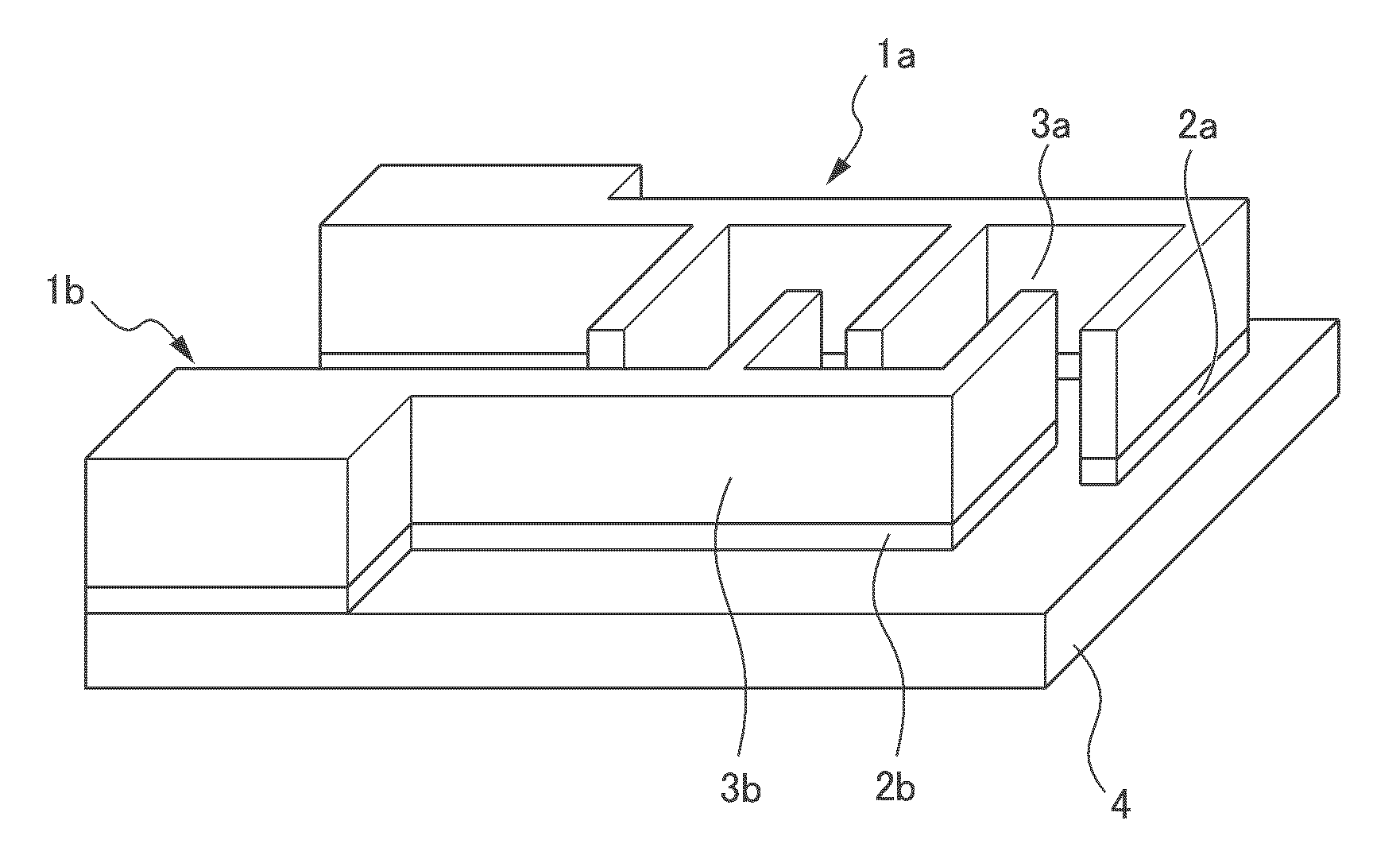
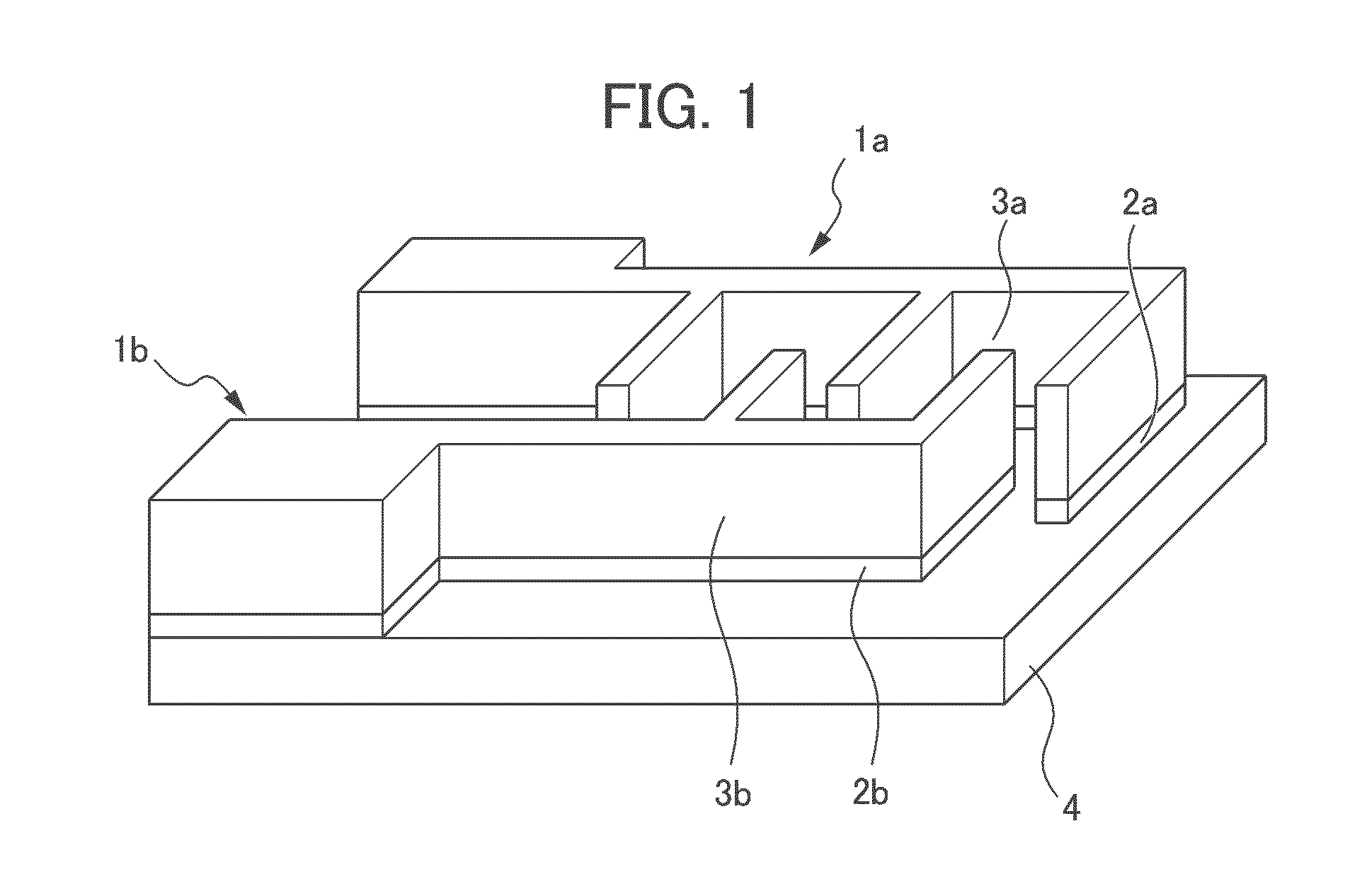
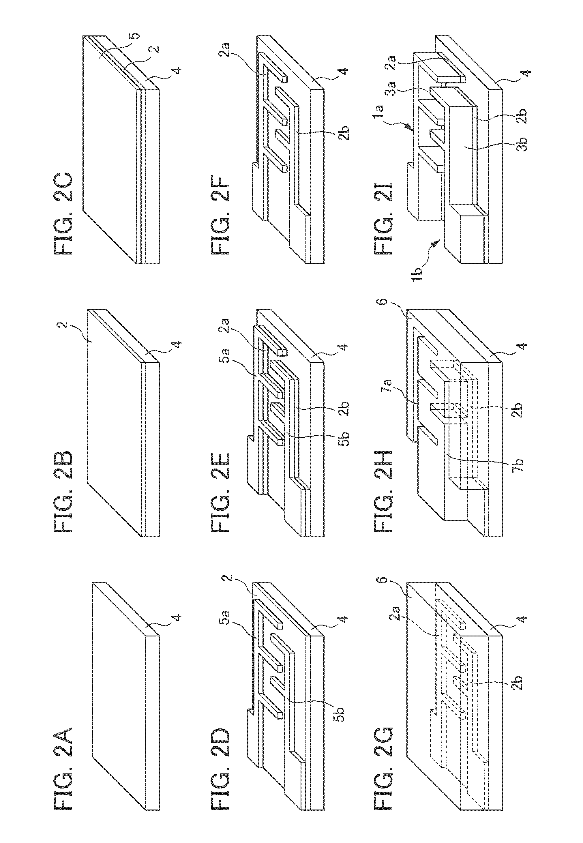
To provide a method for producing a comb-shaped electrode capable of precisely carrying a large amount of active materials on a surface of current collectors with a fine shape. The method for producing comb-shaped electrodes 1a, 1b of the present invention includes a current collector forming step of forming a pair of comb-shaped current collectors 2a, 2b on a surface of a substrate 4, a resist coating step of forming a resist layer 6 on the surface of the substrate 4, and a guide hole forming step of forming guide holes 7a, 7b for forming a positive electrode 1a or a negative electrode 1b, in which a cationic polymerization type resist composition (i), a novolak type resist composition (ii), a chemically-amplified type resist composition (iii), or a radical polymerization type resist composition (iv), is used as a resist composition for forming the resist layer 6.

Description

This application is based on and claims the benefit of priority from Japanese Patent Application Nos. 2010-092864 and 2011-028228, respectively filed on 14 Apr. 2010 and 14 Feb. 2011, the contents of which are incorporated herein by reference.BACKGROUND OF THE INVENTION1. Field of the InventionThe present invention relates to a method for producing a comb-shaped electrode, more specifically, to a method for producing a comb-shaped electrode in which a positive electrode and a negative electrode are respectively formed into a comb shape and oppositely disposed so that the parts of teeth of the comb shapes are alternatively arranged.2. Related ArtSecondary cells capable of being repeatedly charged and discharged have been widely used for various applications starting with portable devices such as cell-phones and laptop personal computers. Furthermore, in recent years, these cells have been used for environment-related fields such as electric powered vehicles and hybrid vehicles.The se...

Claims


Application Information

Patent Timeline
IPC IPC(8): G03F7/20G03F7/023G03F7/027G03F7/038G03F7/039H01L21/027H01M4/139H01M4/66
CPCY02E60/122G03F7/023G03F7/027G03F7/038G03F7/0392H01M4/0452H01M4/13H01M4/626H01M4/78H01M2004/025C25D3/60C25D13/02H01M4/0457Y02E60/10C08L63/00G03F7/0045H01M4/04H01M10/05
Inventor ASAI, TAKAHIROMISUMI, KOICHIONO, TAKASHIKANAMURA, KIYOSHIMUNAKATA, HIROKAZU
Owner TOKYO METROPOLITAN PUBLIC UNIV CORP
Features
  • R&D
  • Intellectual Property
  • Life Sciences
  • Materials
  • Tech Scout
  • Unparalleled Data Quality
  • Higher Quality Content
  • 60% Fewer Hallucinations
Learn More