Augmented delivery catheter and method

Active Publication Date: 2011-11-24
VASCULAR DEV CORP LLC
View PDF5 Cites 73 Cited by
  • Summary
  • Abstract
  • Description
  • Claims
  • Application Information

AI Technical Summary

Benefits of technology

[0026]Certain embodiments of the present disclosure relate to a catheter with an anchoring device to stabilize the catheter tip when in use, such as when infusing, injecting, or delivering substances, devices or other catheters into a patient. The device is comprised generally of a tubular member configured as a catheter with a distal end comprising an outer sheath or tube, an inner sheath or tube, an anchoring mechanism such as a braid with permeable and impermeable portions that enables reliable and stable positioning of the catheter while delivering medicaments (or medical devices or implements such as stents) while allowing a controllable level of blood flow and / or reflux. Other embodiments and alternatives to this device are described in greater detail below.

Problems solved by technology

This results in repeated attempts to cross the lesion, change the catheter / guide wires, predilation with a smaller catheter, reinsertion of the original catheter, and so forth, and adds additional risk and cost to the procedure.
In the case of chronic total occlusions (CTO's), the crossing of the CTO can be extremely difficult as there is a complete occlusion without a lumen that provides resistance to the passage of the guide wire and interventional device.
Similarly, in the endovascular treatment of carotid artery lesions, the acute angles, especially at the origin of the left common carotid artery, create difficulty in advancing the stent delivery catheters as the guide catheters tend to back out of the orifice when the stent delivery catheters are advanced.
This results in repeated attempts at positioning the catheters, changing the catheters, and added risk and cost to the procedure.
The risk of stroke increases with the difficulty of the procedure.
In fact, the same type of problem occurs with regularity anywhere in the body in which a catheter or guide wire is attempted to be pushed through a tight stenosis.
The vessels in the abdomen branch in an acute angle (with respect to the femoral approach) making them difficult to access also.
While the vessels of the lower extremity may be approached with an antegrade puncture in the ipsilateral femoral artery, accessing and treating them may present similar problems as above if the access is done from the contralateral femoral artery.
The combination of the tortuous path the catheters must take, the resistance within the vessel caused by vessel tortuosity or the constricted lesion, and the pulsations of the heart and the aorta combine to make vascular interventions more difficult, more costly, and more risky to the patient than is generally perceived.
The difficulties described above in the current procedures and devices are overcome, as discussed, by changing out the catheters, using other methods and devices, albeit at increased cost and risk, to achieve the desired result.
This leaves chemotherapy as the only alternative, and the effectiveness of the intravenous chemotherapy is limited by the systemic toxicities caused by the drug, including bone marrow suppression, neutropenia, nausea, diarrhea, anorexia, wasting, cachexia, bacterial or viral overgrowth among others.
In this case, there is a likelihood of reflux of the emoblics out of the intended artery causing them to embolize to other unintended arteries and organs.
This may cause a litany of problems and complications, obviously.
While current devices are generally effective in treating the tumor or tumors of the liver, they are somewhat crude and cumbersome to use, as there sometimes is reflux of the toxic chemotherapeutic agent out of the hepatic artery and into arteries supplying the bowel, and the catheter tip may become dislodged from its place in the proper hepatic artery, retracting more proximally and infusing agent into arteries supplying the proximal small bowel, pancreas, spleen, and other organs.
This is of great importance as the dose being infused may be up to ten times the usual intravenous dose, and hence can cause serious side effects if not collected as above before entering the systemic circulation.
Infusion catheters with a balloon on the distal end have been described, but the balloon must be expanded completely to produce stability of the distal catheter and, in doing so, obstructs the flow of the vessel and the flow of the infused material.
This causes the toxic chemotherapeutic agent to flow into vessels other than the intended ones, potentially damaging those tissues supplied by theses vessels, including the pancreas, duodenum, stomach, and spleen among others.
Even if the catheter tip does not move and is stable, there is the possibility of reflux of the toxic agent out of the hepatic artery and into these adjacent arteries as spasm may develop in the hepatic arteries as a result of the infusion of the chemotherapeutic agent, or the infusion rate may exceed the flow in the hepatic artery for some other reason resulting in the volume being infused exceeding the capacity of the artery.
The infused agent then refluxes out of the intended artery and into the surrounding vessels not intended for infusion causing the problems discussed above and even death.
This doubt may prevent thousands, and potentially hundreds of thousands, of patients that may benefit from this therapy from receiving it and prolonging their lives.
In some cases, however, the catheter tip becomes dislodged, usually while attempting to place the second or third coil in the renal artery and the coil embolizes down the aorta and into a lower extremity or other vessel where it must be retrieved by catheters or by surgery.
However, such a rigid collar-like member enables only imprecise degrees of pressure to be axially imparted to the blood vessel, thereby causing unnecessary trauma to the patient.
The prior art catheters and methods of use do not provide a minimal-trauma device that enables predictable and adjustable blood flow through or around a catheter device, prevent reflux as desired, allow centered and / or directional flow of medicament, or accurate, reliable and stable precise positioning.

Method used


Image

  • Augmented delivery catheter and method
  • Augmented delivery catheter and method
  • Augmented delivery catheter and method

Examples


Embodiment Construction

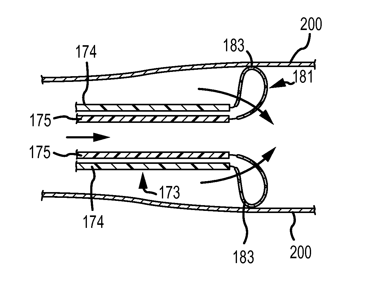
[0095]The present invention relates to a catheter with an anchoring device to stabilize the catheter tip when in use, such as when infusing, injecting, or delivering substances, devices or other catheters into a patient. Thus, for example, the foregoing description of the various embodiments contemplates the use of an expansile member on the tip of the anchor catheter which is designed to anchor the tip and provide stability while maintaining flow in the vessel, and a novel configuration of this member will limit and direct flow beyond the catheter tip to obviate reflux. To achieve stability of the catheter tip, a porous tubular mesh braid is attached to the distal aspect of the catheter in one embodiment. It may be a self expanding braid or it may be controlled by actuator sheaths which will be subsequently described. The braid expands to the vessel wall and stabilizes the catheter tip by contacting the wall, essentially anchoring it to the vessel wall by a gentle annular force.

[00...


PUM


Abstract

The present invention relates to a catheter apparatus with an anchoring device to stabilize the catheter tip when in use, such as when infusing, injecting, or delivering substances, devices or other catheters into a patient. The apparatus according to various embodiments deploys an anchoring device that stabilizes the catheter tip and enables adjustment of the blood flow during use.

Description

CROSS REFERENCE TO RELATED APPLICATIONS[0001]This application claims the benefit of U.S. Provisional Patent Application No. 61 / 395,907, entitled “AUGMENTED DELIVERY CATHETER AND METHOD”, filed on May 19, 2010, and U.S. Provisional Patent Application No. 61 / 400,593, entitled “DEVICES AND METHODS OF TREATING VENOUS DISEASE”, filed on Jul. 30, 2010, the entire disclosure of each of which is incorporated by reference herein.FIELD OF THE INVENTION[0002]This disclosure relates to a catheter with an anchoring device to stabilize the catheter tip when in use, such as when infusing, injecting, or delivering substances, devices or other catheters into a patient.BACKGROUND OF THE INVENTION[0003]Catheter technology is widely utilized to diagnose many abnormalities, to treat vascular disease, to perform vascular interventions, to deliver devices to occlude vessels, and to focally deliver agents to tissues, among other uses. The catheter technology employed will vary depending on the surgical pro...

Claims


Application Information

Patent Timeline
IPC IPC(8): A61M25/04A61M25/09
CPCA61M25/04A61M25/0084
Inventor FULTON, RICHARD E.
Owner VASCULAR DEV CORP LLC
Why Eureka
Try Eureka